Abstract
STATEMENT OF PROBLEM
Currently, many implant systems are developed and divided into two types according to their joint connection: external or internal connection. Regardless of the connection type, screw loosening is the biggest problem in implant-supported restoration.
PURPOSE
The purpose of this study is to assess the difference in stability of abutment screws between the external and internal hexagonal connection types under cyclic loading.
MATERIAL AND METHODS
Each of the 15 samples of external implants and internal abutments were tightened to 30 N/cm with a digital torque gauge, and cemented with a hemispherical metal cap. Each unit was then mounted in a 30° inclined jig. Then each group was divided into 2 sub-groups based on different periods of cyclic loading with the loading machine (30 N/ cm - 300 N/cm,14 Hz: first group 1 × 10⁶, 5 × 10⁶ cyclic loading; second group 3 × 10⁶, 3 × 10⁶ for a total cyclic loading of 6 × 10⁶) The removal torque value of the screw before and after cyclic loading was checked. SPSS statistical software for Windows was used for statistical analysis. Group means were calculated and compared by ANOVA, independent t-test, and paired t-test with α= 0.05.
RESULTS
In the external hexagonal connection, the difference between the removal torque value of the abutment screw before loading, the value after 1 × 10⁶ cyclic loading, and the value after 1 × 10⁶, and additional 5 × 10⁶ cyclic loading was not significant. The difference between the removal torque value after 3 × 10⁶ cyclic loading and after 3 × 10⁶, and additional 3 × 10⁶ cyclic loading was not significant. In the internal hexagonal connection, the difference between the removal torque value before loading and the value after 1 × 10⁶ cyclic loading was not significant, but the value after 1 × 10⁶, and additional 5 × 10⁶ cyclic loading was reduced and the difference was significant (P < .05). In addition, in the internal hexagonal connection, the difference between the removal torque value after 3 × 10⁶ cyclic loading and the value after 3 × 10⁶, and additional 3 × 10⁶ cyclic loading was not significant.
Go to : 
REFERENCES
1.Bra ° nemark PI., Hansson BO., Adell R., Breine U., Lindstro ¨ m J., Halle ´ n O., Ohman A. Osseointegrated implants in the treatment of the edentulous jaw. Experience from a 10-year period. Scand J Plast Reconstr Surg Suppl. 1977. 16:1–132.
2.Adell R., Lekholm U., Rockler B., Bra ° nemark PI. A 15-year study of osseointegrated implants in the treatment of the edentulous jaw. Int J Oral Surg. 1981. 10:387–416.

3.Jemt T., Lekholm U. Oral implant treatment in posterior partially edentulous jaws: a 5-year follow-up report. Int J Oral Maxillofac Implants. 1993. 8:635–40.
4.Nevins M., Langer B. The successful application of osseointegrated implants to the posterior jaw: a long-term retrospective study. Int J Oral Maxillofac Implants. 1993. 8:428–32.
6.Zarb GA., Schmitt A. The longitudinal clinical effectiveness of osseointegrated dental implants: the Toronto study. Part III: Problems and complications encountered. J Prosthet Dent. 1990. 64:185–94.

7.Jemt T., Linde ´ n B., Lekholm U. Failures and complications in 127 consecutively placed fixed partial prostheses supported by Bra ° nemark implants: from prosthetic treatment to first annual checkup. Int J Oral Maxillofac Implants. 1992. 7:40–4.
8.Maeda Y., Satoh T., Sogo M. In vitro differences of stress concentrations for internal and external hex implant-abutment connections: a short communication. J Oral Rehabil. 2006. 33:75–8.

9.Jo ¨ rne ´ us L., Jemt T., Carlsson L. Loads and designs of screw joints for single crowns supported by osseointegrated implants. Int J Oral Maxillofac Implants. 1992. 7:353–9.
10.Binon PP. The effect of implant/abutment hexagonal misfit on screw joint stability. Int J Prosthodont. 1996. 9:149–60.
11.Worthington P., Bolender CL., Taylor TD. The Swedish system of osseointegrated implants: problems and complications encountered during a 4-year trial period. Int J Oral Maxillofac Implants. 1987. 2:77–84.
12.Zarb GA., Schmitt A. The longitudinal clinical effectiveness of osseointegrated dental implants: the Toronto study. Part III: Problems and complications encountered. J Prosthet Dent. 1990. 64:185–94.

13.Hemmings KW., Schmitt A., Zarb GA. Complications and maintenance requirements for fixed prostheses and over-dentures in the edentulous mandible: a 5-year report. Int J Oral Maxillofac Implants. 1994. 9:191–6.
14.Kallus T., Bessing C. Loose gold screws frequently occur in full-arch fixed prostheses supported by osseointegrated implants after 5 years. Int J Oral Maxillofac Implants. 1994. 9:169–78.
15.Jemt T. Fixed implant-supported prostheses in the edentulous maxilla. A five year follow-up report. Clin Oral Implants Res. 1994. 5:142–7.
16.Schwartz-Arad D., Samet N., Samet N. Single tooth replacement of missing molars: a retrospective study of 78 implants. J Periodontol. 1999. 70:449–54.

17.Binon PP. The external hexagonal interface and screw-joint stability: a primer on threaded fasteners. Quintessence Dent Technol. 2000. 23:91–105.
18.Haack JE., Sakaguchi RL., Sun T., Coffey JP. Elongation and preload stress in dental implant abutment screws. Int J Oral Maxillofac Implants. 1995. 10:529–36.
19.ISO/DIS 14801: Dental implants-Dynamic continuous fatigue test. 2003.
20.Haack JE., Sakaguchi RL., Sun T., Coffey JP. Determination of preload stress in dental implant screws. J Dent Res. 1994. 73:202.
21.Yousef H., Luke A., Ricci J., Weiner S. Analysis of changes in implant screws subject to occlusal loading: a preliminary analysis. Implant Dent. 2005. 14:378–82.

22.Norton MR. An in vitro evaluation of the strength of an internal conical interface compared to a butt joint interface in implant design. Clin Oral Implants Res. 1997. 8:290–8.

23.Bahat O., Handelsman M. Use of wide implants and double implants in the posterior jaw: a clinical report. Int J Oral Maxillofac Implants. 1996. 11:379–86.
24.Arvidson K., Bystedt H., Frykholm A., von Konow L., Lothigius E. A 3-year clinical study of Astra dental implants in the treatment of edentulous mandibles. Int J Oral Maxillofac Implants. 1992. 7:321–9.
25.Vigolo P., Fonzi F., Majzoub Z., Cordioli G. An in vitro evaluation of ZiReal abutments with hexagonal connection: in original state and following abutment preparation. Int J Oral Maxillofac Implants. 2005. 20:108–14.
26.Vigolo P., Fonzi F., Majzoub Z., Cordioli G. Evaluation of gold-machined UCLA-type abutments and CAD/CAM titanium abutments with hexagonal external connection and with internal connection. Int J Oral Maxillofac Implants. 2008. 23:247–52.
Go to : 
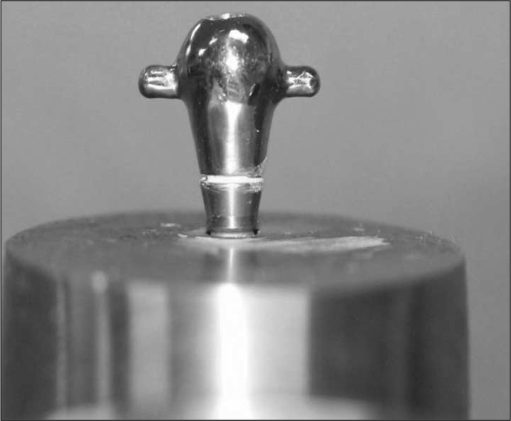 | Fig. 1.The specially customized metal cap; hemisphere shape in order to transmit the applied load to the center of abutment. |
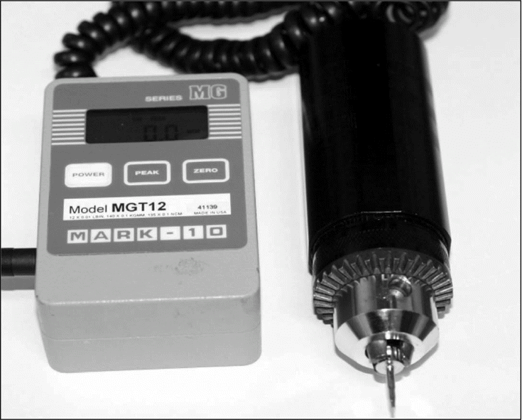 | Fig. 2.Digital torque gauge (MGT12.mark-10. corp. USA). All abutment screws were tightened to 30 N/cm ± 0.5 N/cm with this digital torque gauge and the removal torque values of the screws were recorded. |
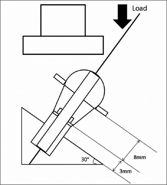 | Fig. 3.Schematic diagram of the specimen. The load was applied on the hemispheric metal cap at 30° and the distance was 11 mm from the exposed position of the fixture to the center of the hemisphere. |
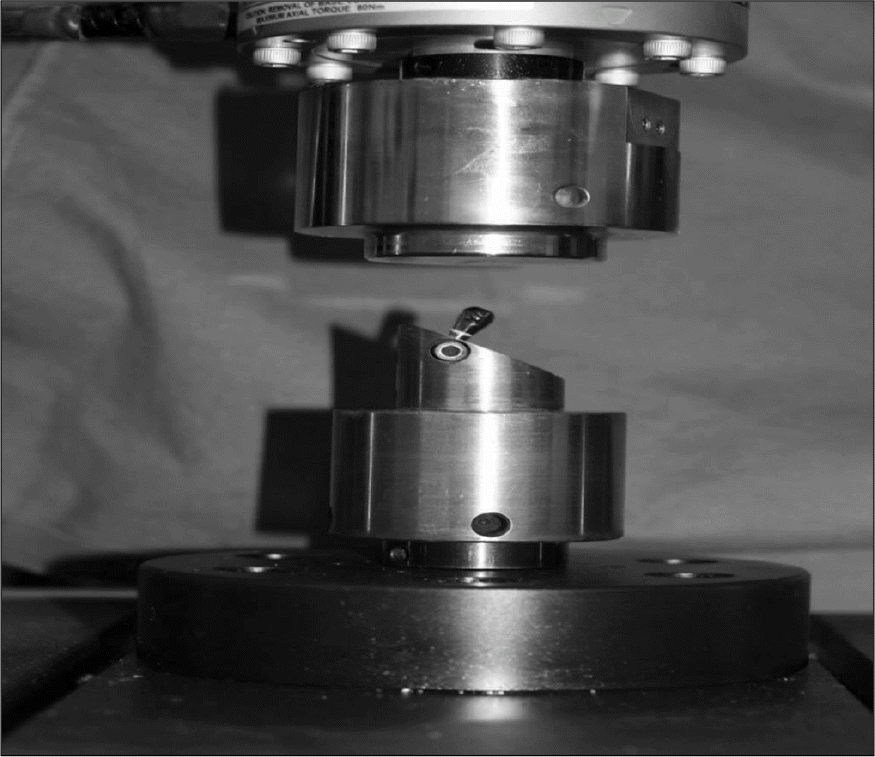 | Fig. 4.The specimen is mounted in the customized jig with 30° inclined plane to be loaded with load machine (Instron model 8871. USA). |
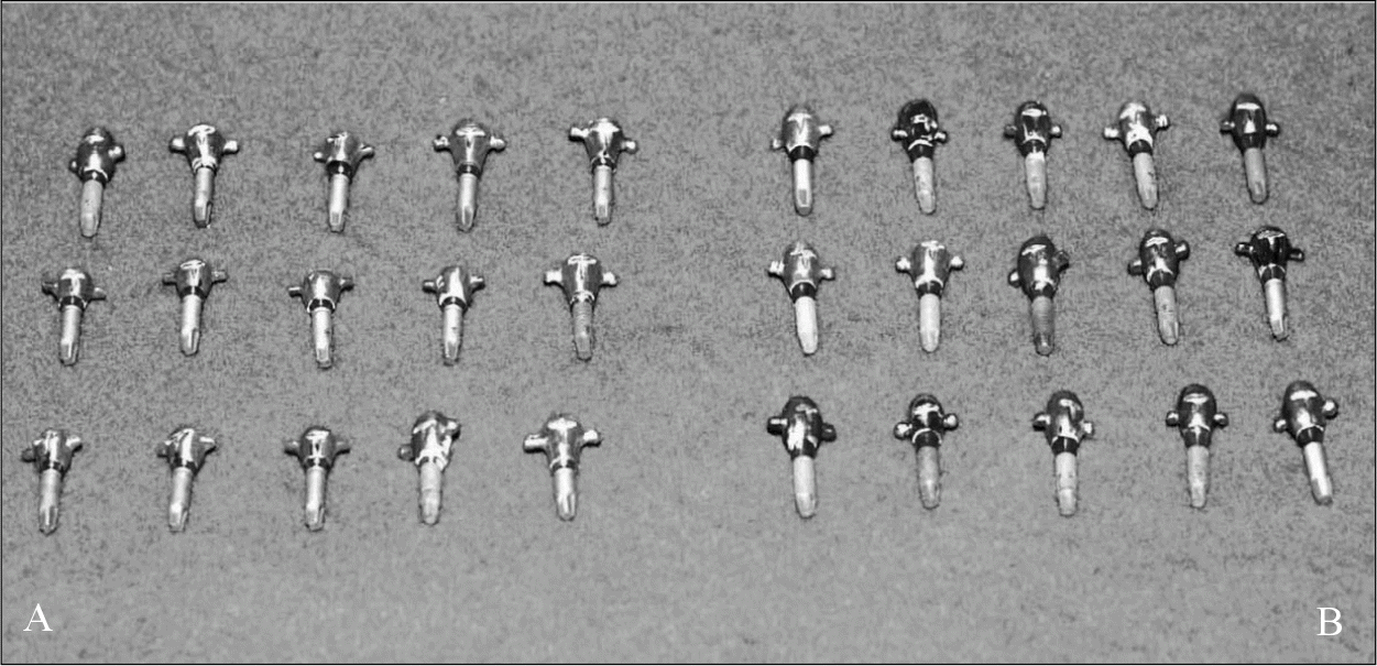 | Fig. 5.Group A, B Group A: External hexagonal connection of the abutment and fixture (Left). Group B: Internal hexagonal connection of the abutment and fixture (Right). |
Table I.
Materials of tested specimens
Table II.
Assessment of the removal torque value in Group A-a and Group A-b after cyclic loading
Table III.
Comparison of the removal torque value after total 6 × 10⁶ cyclic loading between Group A-a and Group A-b
| Group | Cyclic loading | Mean removal torque value (N/cm) | SD | t/p value |
|---|---|---|---|---|
| A-a | 1 × 10⁶, and additional 5 × 10⁶ | 17.79 | 1.28 | |
| A-b | 3 × 10⁶, and additional 3 × 10⁶ | 18.78 | 0.25 | -1.673/.118 |
Table IV.
Assessment of the removal torque value in Group B-a and Group B-b after cyclic loading
| Group | Cyclic loading | Mean removal torque value (N/cm) | SD | t/p value |
|---|---|---|---|---|
| Before loading | 30.32 | 0.31 | .875/.397 | |
| B-a | 1 × 10⁶ | 19.29 | 1.28 | -1.239/.223 |
| 1 × 10⁶, and additional 5 × 10⁶ | 11.40 | 1.25 | 14.096∗∗∗/.000 | |
| Before loading | 30.18 | 0.53 | 1.206/.236 | |
| B-b | 3 × 10⁶ | 18.84 | 1.09 | -.278/.783 |
| 3 × 10⁶, and additional 3 × 10⁶ | 18.20 | 0.91 | .666/.510 |
Table V
. Comparison of the removal torque value after total 6 × 10⁶ cyclic loading between Group A-a and Group A-b
| Group | Cyclic loading | Mean removal torque value (N/cm) | SD | t/p value |
|---|---|---|---|---|
| B-a | 1 × 10⁶, and additional 5 × 10⁶ | 11.4 | 1.25 | |
| B-b | 3 × 10⁶, and additional 3 × 10⁶ | 18.2 | 0.91 | -10.694∗∗∗/.000 |
Table VI.
Comparison of the removal torque value after cyclic loading between Group A and Group B
| Cyclic loading | Group | Mean removal torque value (N/cm) | SD | t/p value |
|---|---|---|---|---|
| 1 × 10⁶ | A-a | 19.05 | 1.11 | -0.463 |
| B-a | 19.29 | 1.28 | /.654 | |
| 1 × 10⁶, and additional 5 × 10⁶ | A-a | 17.79 | 1.28 | 10.834∗∗∗ |
| B-a | 11.40 | 1.25 | /.000 | |
| 3 × 10⁶ | A-b | 19.36 | 0.64 | .808 |
| B-a | 18.84 | 1.09 | /.465 | |
| 3 × 10⁶, and additional 3 × 10⁶ | A-b | 18.78 | 0.26 | 1.329 |
| B-a | 18.20 | 0.91 | /.255 |


 PDF
PDF ePub
ePub Citation
 Print
Print


 XML Download