Abstract
Introduction
Materials and Methods
Results
Conclusion
References
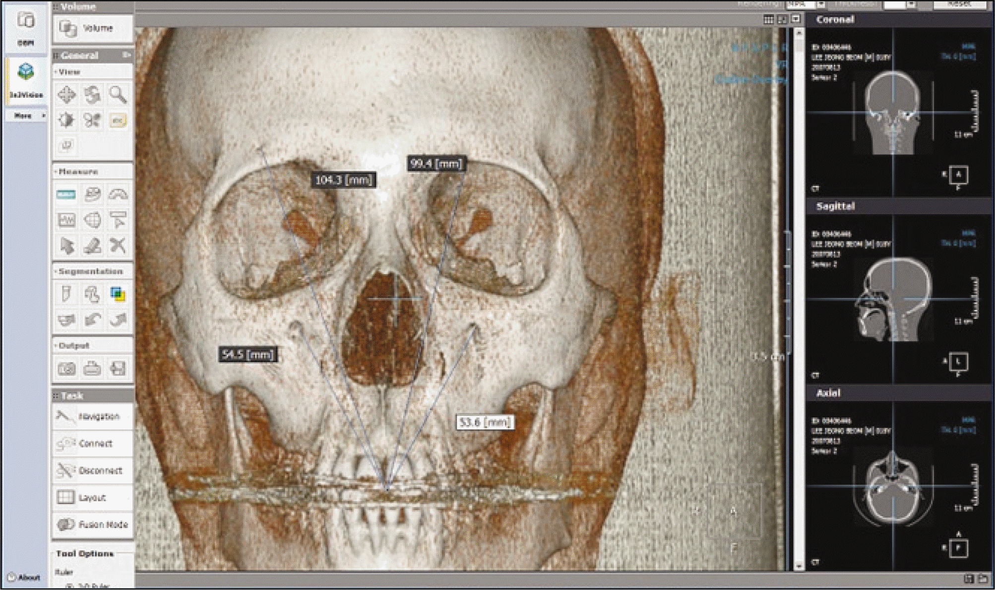 | Fig. 1.Measuring the distance between 4 reference points and contact point of maxillary central incisors on a In2Vision 3-dimensional surgical navigation system. |
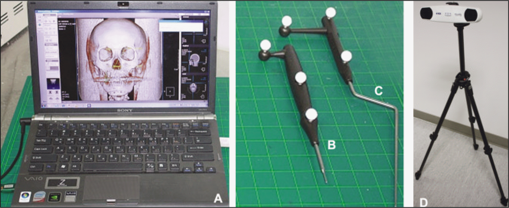 | Fig. 2.Used tools in this study. A was the computer system displaying In2Vision system, B was the registration probe, C was the navigation probe, D was the infrared VICRA Polaris camera. |
 | Fig. 3.Preparation and measurement of rapid prototype model in this study. A. Microscrews were implanted in nasion, both supraorbital foramen, contact point of maxillary central incisors for the reproducible measurement. B. Gradation was drawn over the maxillary canine and first molar and SAS was implanted in mesiobuccal cusp tip of maxillary first molar. C. Measuring the vertical distance between left supraorbital foramen and mesiobuccal cusp tip of left maxillary first molar. (SAS: skeletal anchoring system) |
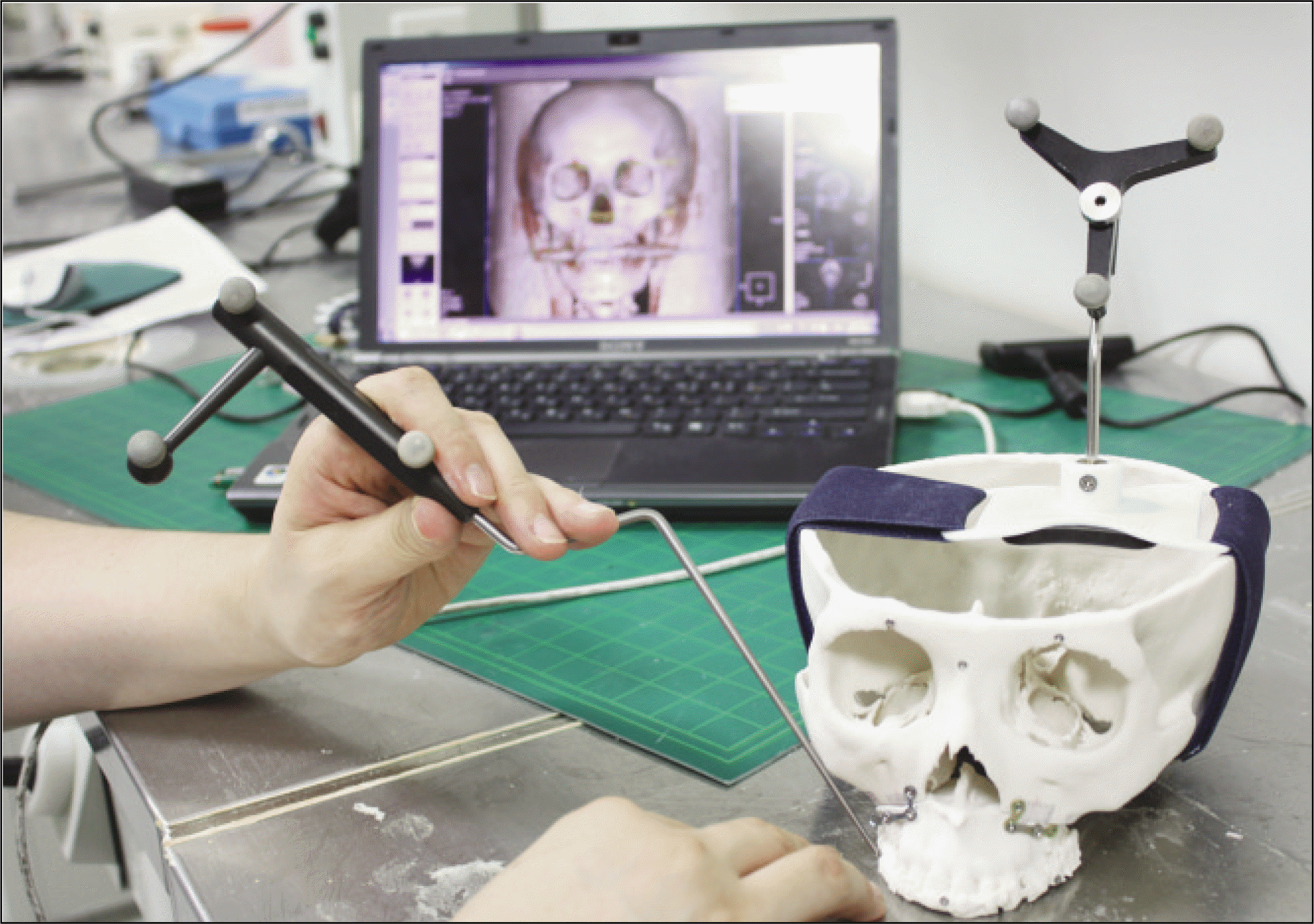 | Fig. 4.Tracking the points by using of In2Vision 3 dimensional surgical navigation system and Polaris Vicra tracking device. |
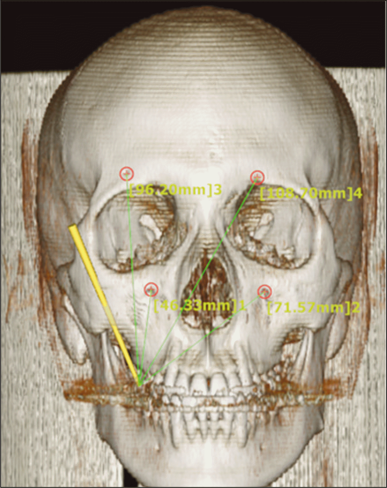 | Fig. 5.Measuring the distance between 4 reference points on skull and ICP after simulation surgery on RP model (ICP: interincisal contact point, RP: rapid prototyping) |
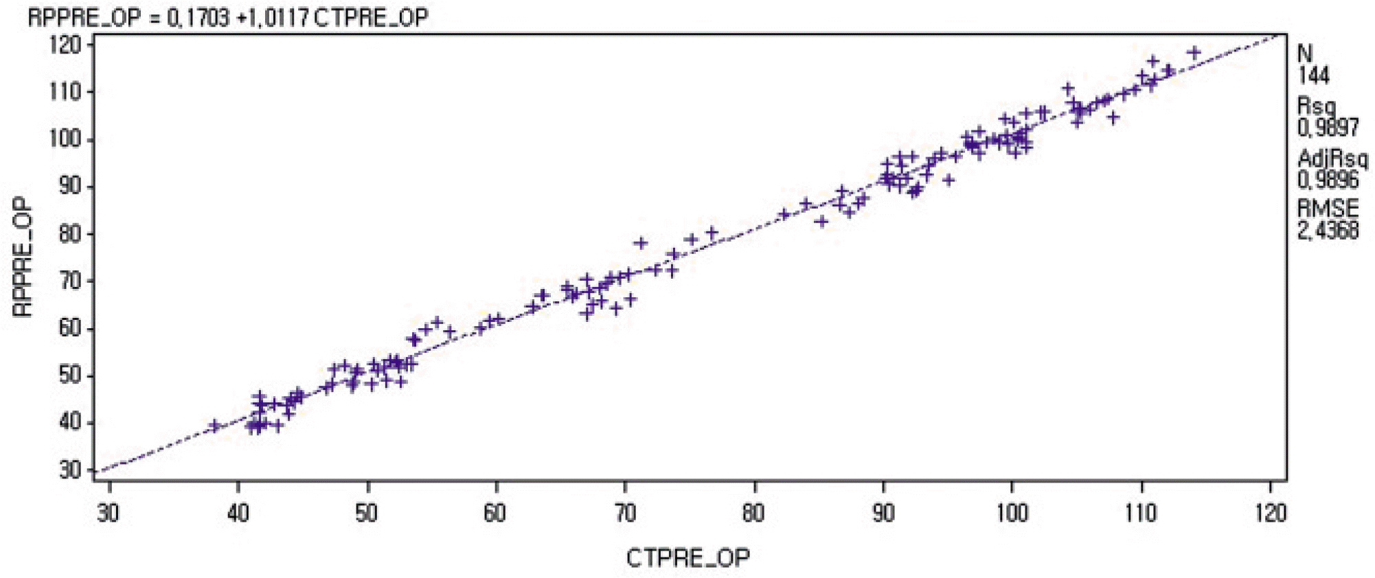 | Fig. 6.RMSE analysis graph of measured distances between 3D CT image in X axis and RP model in Y axis before surgery.(mm) (RMSE: root mean square error, 3D CT: 3 dimensional computed tomography, RP: rapid prototyping) |
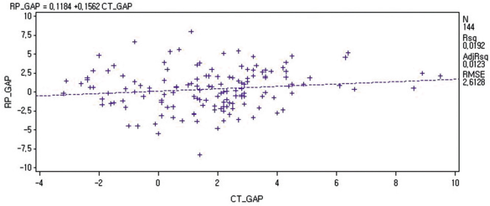 | Fig. 7.RMSE analysis graph showing changes between before and after surgery in measured distances of 3D CT image in X axis and RP model in Y axis.(mm) (RMSE: root mean square error, 3D CT: 3 dimensional computed tomography, RP: rapid prototyping) |
Table 1.
Table 2.
Table 3.
Table 4.
(3D CT: 3 dimensional computed tomography, RIF: right infraorbital foramen, LIF: left infraorbital foramen, RSF: right supraorbital foramen, LSF: left supraorbital foramen, RMBC: right mesiobuccal cuspal tip, ICP: interincisal contact point, LMBC: left mesiobuccal cuspal tip) * Comparison with parameters in Table 1, P<0.05
Table 5.
Table 6.
(3D CT: 3 dimensional computed tomography, RIF: right infraorbital foramen, LIF: left infraorbital foramen, RSF: right supraorbital foramen, LSF: left supraorbital foramen, RMBC: right mesiobuccal cuspal tip, ICP: interincisal contact point, LMBC: left mesiobuccal cuspal tip) * Comparison with parameters in Table 3, P<0.05


 PDF
PDF ePub
ePub Citation
 Print
Print


 XML Download