

 PDF
PDF ePub
ePub Citation
 Print
Print


INTRODUCTION
It is generally believed that the initiation, growth, and rupture of intracranial aneurysms result from bio-mechanical interaction between exo-vascular environment and endo-vascular hemodynamics.1 To date, the best way to obtain information about the intracranial vasculature is mainly to rely on catheter angiography. However, it provides only structural understanding, not hemodynamic factors, and can potentially be harmful.2
One of the ways to simulate and analyze hemodynamic factors is to utilize computational fluid dynamics (CFD) tools, which provide an effective and safe method to assess velocity magnitude, fluid streamlines, wall shear stress (WSS) distribution, and oscillatory shear index (OSI). Since the current technology limits the ability to measure these hemodynamic factors in vivo, the CFD simulation studies are valuable in the exploration of the cerebral vascular system.34567
In the CFD simulation, the geometry of the model is an important factor that influences the flow behaviors. Thus, segmentation of an artery could greatly affect the intra-aneurysmal hemodynamics. The irregular geometries specific to each patient, including arteries with large curvature, non-planarity, and many side branches, make truncation difficult. Excluding geometrical factors may lead to low simulation accuracy, and may even lead to incorrect conclusions.48 Similarly, inclusion of vessels that can be ignored wastes computational effort,910 and different segmentation lengths of the parent artery harboring the target lesion can lead to quite different flow patterns.11 Despite these studies, the minimum inlet length and outlet extension length that ensures simulation accuracy is still not clear.
Another key factor influencing the accuracy of CFD simulation is the inlet and outlet boundary conditions (BCs). Some researchers model the inlet velocity as a flat (plug) profile across the inlet section, and others rely more on the Womersley theory to model the flow, which is thought to accomplish a fully developed shape across the inlet section.1213 Although the Womersley inlet BC is known to more closely approximate what is seen in reality, it may be even worse than the plug flow BC in some cases.1415 For the outlet, a few studies examined the influence of vasculature extension on the CFD results, while many researchers just applied zero pressure (p=0) as the outlet BC.1617 Instead of zero pressure, realistic waveform patient-specific pressure data can be used as the outlet BC. Outflow (traction-free) is also an outlet BC commonly used in fully-developed flows where the diffusion flux for all flow variables in the exit direction is zero (normal gradient is zero). The influence of different inlet/outlet BCs and inlet/outlet length truncation on the CFD result has yet to be discussed.
The purpose of this paper is to assess the influence of the segmentation of parent arteries and the BCs on the simulated hemodynamic factors of intracranial aneurysms such as velocity pattern, streamline, WSS, and OSI. Hemodynamic factors at the systolic time were compared and analyzed using the CFD simulation results. These analyses results would provide useful guide in truncating aneurysm models and selecting appropriate BCs for more accurate CFD simulations.
MATERIALS AND METHODS
Patient and aneurysm models
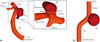
This study protocol was approved by our Institutional Review Board, and informed consent was waived. In order to analyze the combination of different BCs and boundary positions, digital subtraction angiography images of a middle cerebral artery bifurcation aneurysm were gathered from a 72-year-old female patient using a Philips Integris system (Philips Medical Systems, Best, the Netherlands). These images were reconstructed to three-dimensional surface models, and then the aneurysm artery model was selected and truncated. Fig. 1A shows one of these truncating models with an inlet length (L) of 6D (D: inlet diameter) and an outlet length (K) of 3.5d (d: outlet diameter). L and K mean the distances between the inlet and outlet positions and the center of the aneurysm, respectively. Different combinations of BCs were applied to this truncated model to examine the influence of BCs on hemodynamic factors (Table 1). In addition, the inlet and outlet lengths from the aneurysm were also changed, considering the inlet velocity magnitude variation at different inlet positions caused by the change in artery diameter under the same flow rate waveform. Eight truncating models with L varying from 3D to 30D and a fixed K=3.5d were used to analyze the influence of inlet lengths and inlet BCs. Also, four truncating models with a fixed L=26D and K varying from 1d to 4d were selected to analyze the influence of outlet lengths.
In addition, the ideal model for the side wall intracranial aneurysm with a proximal curvature was created, which was composed of a curved pipe for artery and a sphere for aneurysm, as shown in Fig. 1B. The artery diameter was the same as the inlet and outlet diameter (D=d=3.5 mm), and the aneurysm sac diameter was set to be 11 mm. The proximal curvature was designed to begin at L=2D and end at L=4D. The ideal model was truncated with the inlet lengths, ranged from 2D to 6D, and the outlet length of 3.5d, and the Womersley flow and zero pressure were applied as both inlet and outlet BCs to assess the influence of segmentation on the hemodynamic factors of the sidewall aneurysm with a proximal curvature.
Vascular models
Three-dimensional surface models were imported into ICEM CFD 14.2™ software (ANSYS Inc., Canonsburg, PA, USA) to generate volumetric finite-element grids used for CFD calculations. Unstructured grids of tetrahedrons and prism elements were used for volume meshing with a consistent mesh density. For the patient-specific truncated models, the element number varied according to the volume differences of the truncated models, but these models occupied the same element density, which was about 2800 elements/mm3. The total element number varied from 1.8 million to 8.34 million, which was enough to obtain grid-free CFD simulation results.15 For the ideal model, three million tetrahedrons and prism elements were generated with a density of 1868 elements/mm3. Tetrahedral element grids were generated part by part with different mesh densities for surface meshing. In all of these models, the mesh minimum resolution was about 0.1 mm for the wall and the inlets and outlets, and 0.05 mm for the aneurysm sacs.
Blood flow models
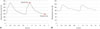
The blood flow was modeled as Newtonian incompressible fluid with a density of 1060 kg/m3 and a viscosity of 4 mPa·s. The blood vessel wall geometries were assumed to be rigid with a no-slip BC. The solver was set on the second-order, high-resolution advection differencing scheme by default. We used the waveform of flow rate Q(t), demonstrated by Kono, et al.,18 to calculate the inlet velocity of BCs (Fig. 2A). Considering the pulse cycle convergence independence, two cardiac cycles were calculated. The first cycle was used to examine solution convergence, and the results of the second cycle were used for analysis. The systolic time on the second cardiac cycle was about 1.19 s, and the diastolic time was about 1.84 s. Both a parabolic velocity distribution based on Womersley solution and a flat (plug flow) velocity distribution were defined across the inlet sections. The parabolic Womersley velocity profile was calculated according to the predefined procedure19 and applied to the inlet by User-Defined Function (UDF). For the plug flow BC, the average velocity of the inlet entrance section was derived by dividing the flow rate Q(t) with the inlet cross-sectional area, and UDF was then used to apply the resulting flat velocity profile to the inlet.
The waveform pressure for the outlet BC is shown in Fig. 2B. Since it was used only to compare with the other outlet BCs (zero pressure and outflow), the averaged waveform pressure, measured with applanation tonometry in the cerebral artery by Reymond, et al.,12 was used as a reference and applied to the outlet using UDF. The convergence criteria for residuals and momentum were set to 10-4, and a cycle of 1000 time steps was calculated with each step lasting 0.00184 s. The number of maximum iterations was 500 for each time step.
Hemodynamic factor analysis
The hemodynamic factors were evaluated and shown via the CFD post-processing toolkit (ANSYS Inc., Canonsburg, PA, USA). Instantaneous streamlines were calculated for each case at the systolic time, and the origins of these streamlines were all at the inlet to avoid influencing the results by flow visualizations. Velocity contours of the neck section and WSS in the aneurysm sac at the peak of systole were calculated and compared. The OSI analysis was conducted using Matlab (Mathworks, Natick, MA, USA), and then the OSI values for the aneurysm sac were imported and visualized via the CFD post-processing toolkit.
RESULTS
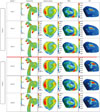
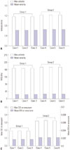
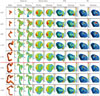
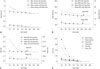
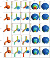
The simulation results for the patient-specific aneurysm model (Fig. 1A) with six combinations of inlet and outlet BCs (Table 1) are shown in Fig. 3. Hemodynamic factors such as streamlines, velocity contours in the neck cross-section, and WSS and OSI distributions in the aneurysm sac at the second systolic time were compared. The first three cases under the same inlet BC of plug velocity profile and three different outlet BCs showed quite similar results, whereas the last three cases changed the inlet BC to the Womersley velocity profile. However, these two groups were different in all these hemodynamic factors. The last three cases under the Womersley flow inlet BC presented larger areas of contours corresponding to higher hemodynamic factors than those under the plug flow inlet BC. Fig. 4 summarizes the mean and maximum values of hemodynamic factors for different combinations of inlet and outlet BCs. As expected from Fig. 3, each hemodynamic factor was almost the same for each group. The differences in the maximum velocity, WSS, and OSI between these two groups were 6.5%, 4.1%, and 66.9%, respectively.
Fig. 5 compares the hemodynamic factors at the systolic time for different inlet BCs and inlet lengths (from 3D to 30D), when a fixed outlet length of K=3.5d was used and the outlet BC was set to zero pressure. The arrows indicate the points where the values of hemodynamic factors are considered most different from each contour. When the inlet length was small (L<16D), the hemodynamic factors were significantly different under the two different inlet BCs. For both the inlet BCs, the hemodynamic factors were also dependent on the inlet length. However, when the inlet length was large enough (L>20D), the contours for hemodynamic factors became quite similar regardless of which inlet BC was applied.
Several important hemodynamic factors should be noted along the inlet length (Fig. 6). All the values for hemodynamic factors decreased with increasing the inlet length regardless of the inlet BC; however, the values became almost the same when L>20D. When L=3D, the percent error of the maximum OSI value between two inlet BCs was the largest and its value was as high as 116.1%. However, when L>20D, all the errors caused by two inlet BCs were around zero, and the values for hemodynamic factors remained almost unchanged for different inlet lengths and BCs.
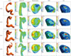
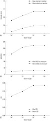
Fig. 7 illustrates the contour of representative hemodynamic factors at the systolic time for various outlet lengths when the inlet length was fixed to L=26D and the plug flow and the zero pressure conditions were used as the inlet and outlet BCs, respectively. Several important hemodynamic factors were also calculated and presented along the outlet length (Fig. 8). Similar to the inlet length variation, the values for hemodynamic factors changed depending on the outlet length. As the outlet length was increased, all the values for hemodynamic factors increased up to K=2d and became constant thereafter.
In applying same simulation protocol to side wall type aneurysm in ideal model (Fig. 1B), almost same result was obtained. Furthermore, when the inlet was truncated near the curved area (L≤3D), the inflow angle tended to become larger than the others. This indicates that blood flows into the aneurysm sac and rotates at a higher velocity, leading to a larger impact area and a higher WSS value. In contrast, for the inlet positions located beyond the curved part (L≥4D), there was little difference in the flow pattern among them, and the hemodynamic behavior for each case became similar (Fig. 9).
DISCUSSION
From the CFD simulation with six different combinations of inlet and outlet BCs, it was found that the velocity and WSS differences were relatively small under the two different inlet BCs while OSI showed a large difference between these two different inlet BCs (Figs. 3 and 4). However, it should be noted that there was almost no variation in the hemodynamic factors with different outlet BCs when the inlet BC was the same. Therefore, hemodynamic factors were found to be greatly affected by inlet BCs and much less sensitive to outlet BCs.
It is known that the inlet position has an influence on the hemodynamic factors, but the best way to define the inlet position is still unclear when dealing with a patient-specific model. In order to better understand the effect of both the inlet position and the inlet BC on the hemodynamic factors, patientspecific aneurysm models with different inlet lengths and BCs should be constructed and analyzed. When the inlet length is short, all these hemodynamic factors show visible differences and these differences decrease with increasing the inlet length (Figs. 5 and 6). While the maximum OSI value showed the largest variation, the error for the mean velocity between two different inlet BCs was the smallest due to the same flow rate being applied. The percent errors for maximum hemodynamic factors values are more obvious than corresponding mean hemodynamic factors. When the inlet length was large enough (L>20D), these errors became all negligible. This means that the inlet length is the more important factor to be considered than the inlet BC when evaluating the hemodynamic factors using CFD analysis, and the inlet length should be long enough, at least 20 times as large as the artery diameter; otherwise, inaccurate hemodynamic factors can be obtained from the CFD analysis. It should also be noted that when the inlet length was large enough for the aneurysm analysis model, the simpler flat velocity profile could be used as the inlet BC instead of the relatively more complicated parabolic Womersley velocity profile since these two different inlet BCs result in almost the same hemodynamic factors.
Since the outlet length can also influence the simulated hemodynamic factors like the inlet length, the effect of the outlet length on the hemodynamic factors was investigated by varying the outlet length (Figs. 7 and 8). When K=0d, which indicates the outlets are just holes on the parent artery, the values for hemodynamic factors were quite different from other outlet lengths. When the outlet length was larger than twice the outlet diameter, the values for hemodynamic factors remained almost unchanged. It is interesting to note that the outlet length should not be too long (K>2d), compared to the inlet length requirement (L>20D), in order to perform more reliable evaluation of the hemodynamic factors.
There are a few limitations in our study. Firstly, the flow rate (Q) and the waveform pressure used for defining the inlet and outlet BCs were taken from the previous work,1218 not from the patient-specific measurement data. Therefore, values calculated for the hemodynamic factors might not accurately reflect the hemodynamic behavior of the patient-specific aneurysm model used for our analysis. However it is reported that the flow patterns inside the aneurysm are not influenced by flow rate variations as large as 25%.10 The aim of this work is also to investigate the effects of different combinations of BCs and inlet/outlet positions on the hemodynamic behaviors, therefore, the variation tendency among each simulation case is considered more important than the values for the hemodynamic factors themselves. Secondly, the data in this study was archived from one patient. There could be a variety of restriction in applying CFD simulation on real clinical data. Therefore, we created an imaginary model to verify our assumption, which resultantly proved to support our conclusion; at least about the impact of inlet segmentation. Other limitations are a rigid arterial wall assumption, Newtonian fluid model for blood, and no fluid-wall interaction and vascular compliance, which are common limitations in most of the CFD hemodynamic analyses. Future research is necessary to further investigate the influence of these limitations on the hemodynamic characteristics.
In conclusion, the simulation results showed that the hemodynamic factors are highly sensitive to the inlet BC and length, while they were little affected by the outlet BC. When the inlet length was long enough, two different inlet BCs including the uniform plug and the parabolic Womersley flows lead to almost the same hemodynamic factors. Therefore, the inlet length should be set at least 20 times larger than the inlet diameter (L≥20D). In contrast, the outlet length larger than twice the outlet diameter (K≥2d) is required to obtain reliable results. The results of this work can provide an insight into how to truncate models and help select an appropriate inlet/outlet BCs for more accurate CFD simulations of intracranial aneurysms.

 XML Download