

 PDF
PDF ePub
ePub Citation
 Print
Print


INTRODUCTION
Current treatment methods for limb deformity consist of acute correction by osteotomy and gradual correction using distraction osteogenesis.1-4 Although the procedure is more complex and time consuming, gradual correction offers several advantages over acute correction. Gradual correction allows for relatively large amount of correction with little risk of neurovascular compromise and permits concomitant limb lengthening without bone grafting, if needed.1,2 Gradual correction usually requires Adexternal fixators which hold corticotomized bone during new bone formation and rotate segments to the desired direction.
There have been various types of external fixators available, which generally could be classified into two types, ring and unilateral fixators.5 Both types of fixators provide mechanical stability and controlled distraction to be suitable for new bone formation bydistraction osteogenesis.6,7 However, in terms of angular deformity correction, unilateral fixators have played a limited role because traditional unilateral fixators are usually lack of hinge system and, even if some unilateral fixators are designed to include hinge system, exact realignment is difficult to achieve due to limited capability of hinge placement.8 Ring fixators are constructed with hinge-motor system which allows for the correction of angular deformity.5,6,9-11 Versatile placement of hinge on the circular frame offers capability to achieve realignment without creating secondary deformities. Many investigators have used and recommended ring fixators for gradual correction of limb deformity, ranging from simple one plane angular deformity to more complex three plane deformity.5,6,9-11 However, the use of bulky ring fixators with hinge system requires complex planning, laborious pre-construction of frame and protracted learning curve of surgeons and renders discomfort to patients.5,6 To alleviate surgeon's toil and minimize patient's inconvenience, there have been several efforts to use unilateral fixators for the deformity correction in selected cases. Some authors introduced the technique of immediate correction and then limb length819ening by using a unilateral fixator,3,4,7 whereas others used modified unilateral fixators which have translator system. 12-16 Theoretically, translator system can correct the secondary displacement which may develop when the hinge of unilateral fixator could not be placed on the Center of Rotational Angulation (CORA) to provide exact realignment.
Dyna-ATC is a unilateral external fixator which has a lengthener, angulator and translator system. The angulator is an active hinge system which is designed for the correction of angular deformity, and translator system allows for compensation of secondary displacement. However, the methods to calculate the secondary displacement and the rate of angular correction for active hinge system have not well been described in the literature.
Therefore, the objectives of this study were two-folds. First objective was to introduce the methods required for the angular deformity correction, using Dyna-ATC which included surgical technique, calculation methods for secondary displacement and the rate of angular correction. Second objective was to determine whether Dyna-ATC could correct angular deformities of lower limbs by means of radiographic measurements.
MATERIALS AND METHODS
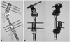
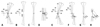
Dyna-ATC (Fig. 1)
Dyna-ATC was approved by Korean Food and Drug Adperministration as a unilateral fixator and launched on market in 2003. Dyna-ATC is made of metal alloy, and main body consists of a cylindrical lengthener bar, two angulators, a translator and a side clamp. The lengthener bar is 18 cm in length and 2 cm in diameter. It permits maximum 7 cm of length change. Translator is connected to the lengthener bar and allows 2 cm of translation on both sides. Two angulators are positioned at right angle, and each angulator provides 30 degrees of rotation on both sides. Side clamp is located at the end of the body with screw holes. There are two types of Dyna-ATC, Standard-type and T-type, according to the type of side clamp. Side clamp of Standard-type has 5 screw holes parallel to the body and that of T-type could be constructed to have maximum 4 screw holes perpendicular to the body. T-type is useful, especially for the proximal tibia. Dyna-ATC permits the attachment of various types of clamps on the lengthener bar including standard, single, universal and arc clamps. This modular system allows for the correction of two plane angular deformity; one plane translational deformity and concomitant lengthening.
Application of dyna-ATC
For less risk of neurovascular damage, less muscle penetration, and better patient's comfort, Dyna-ATC is usually placed laterally on femur and medially on tibia regardless of whether the deformity is varus or valgus.
Proximal tibia deformity (Fig. 8)
T-type Dyna-ATC is designed especially for the correction of proximal tibia angular deformity. Usually four screws are enough for tibia fixation. Two screws are placed on proximal fragment parallel to the transverse plane, and the other two screws are placed on distal fragment parallel to the coronal plane. First, we start with proximal posterior screw about 1.5 cm distal to the joint line or 1 cm distal to the growth plate (if still open). This screw is placed parallel to the growth plate or proximal tibia joint orientation line on the coronal plane and on the posterior cortical line of diaphysis extended proximally in the sagittal plane. Proper placement of the first screw in sagittal plane is important because the more posterior placement usually irritates pesanserinus and the more anterior placement leaves less room for the second screw. We usually use cannulated drilling over the guide-wire technique and image intensifier, which provides easy and proper placement of first screw. Then, most distal screw is inserted perpendicular to the normal mechanical axis. At this time, pre-constructed Dyna-ATC with clamp unit could serve as a guide for the distal screw placement. To achieve effective correction of angular deformity, the angulator of Dyna-ATC should be on the plane of angular deformity. For example, to correct pure varus or valgus deformity, the angulator should be on the coronal plane. If not, secondary procurvatum or antecurvatum deformities may result. This inadvertent sagittal plane deformity may be large enough to cause clinical problems in cases when large amount of varus or valgus correction is needed. After Dyna-ATC with clamp unit is secured on proximal and distal screw, additional two screws are inserted through the clamp holes. Second distal screw is inserted parallel to the most distal screw and proximal anterior screw is placed with about 5 degrees of convergent angle to the posterior screw to avoid possible damage to the growth plate of tibial tuberosity. Corticotomy is performed just below the tibial tuberosity when the growth plate is still open, or in rare cases just proximal to the tibial tuberosity. For cases without shortening, dome-shaped corticotomy is useful to achieve correction of angular deformity with no or minimal lengthening. Fibular osteotomy could be combined to aid angular correction if needed. We routinely perform fasciotomy to avoid possible risk of the compartment syndrome after corticotomy on the proximal tibia. We make skin incision for tibia corticotomymore laterally, then usual medial incision along the anterior tibial crest. After corticotomy performed, the fascia of anterior compartment is exposed with blunt dissection through the same incision for corticotomy. With fasciotome or narrow scissors, inverted L-shaped fasciotomy could be performed without additional skin incision.
Distal femur deformity (Fig. 9)
Standard type is useful for angular correction of femoral deformities. Usually, distal Schanz screw is placed first at distal epi-metaphyseal junction or just proximal to distal femoral growth plate (if it is still open) perpendicular to the normal joint orientation line. If there is no deformity on distal femoral condyles, this screw usually has 3 degrees of divergent angle to distal femoral joint orientation line. Next, second Schanz screw is placed at the level of lesser trochanter perpendicular to normal mechanical axis. Then, Dyna-ATC with Standard clamp unit is assembled and secured over the screws. If two screws are inserted properly, the amount of angulation of Dyna-ATC will be equal to that of angular deformity. These two screws should be parallel in transverse plane. If not, it is very difficult to apply Dyna-ATC, because standard clamp of Dyna-ATC does not permit unparallel placement of screws in transverse plane as in many other unilateral fixators. One tip for the insertion of second screw parallel to the first screw is to use Dyna-ATC as a template for second screw insertion. First, angulator of Dyna-ATC is set up to the degrees of angular deformity. After insertion of first screw, Dyna-ATC with Standard clamp unit is secured on the screw. Then, insert second screw through the screw hole of Standard clamp on the other side. This screw hole of Standard clamp will serve as a guide for parallel placement of second screw in transverse plane. If first screw is placed properly and the calculation of angular deformity is correct, second screw could be placed perpendicular to mechanical axis line as well. After Dyna-ATC with Standard clamp unit secured on proximal and distal screws, additional screws could be inserted through the other holes of clamps. Usually, 3 Schanz screws per segment are enough to provide sound mechanical stability for the distraction osteogenesis for femur. Side clamp of Standard Dyna-ATC has 5 screw holes with different distance, which provides more versatile screw placement. For cases in which CORA is located closer to the physis, screws could be placed on distal holes of clamp to make it possible to perform corticotomy more distally. Maximal 4 screws can be placed to the proximal femoral fragment through a Standard clamp. If the proximal femoral fragment is so long that one Standard clamp is not enough to afford stability, a Single clamp can be added to improve stability. One of the concerns in unilateral fixation on the femur is mechanical instability which comes from parallel placement of screws with limited spread on the relatively long segment. Usually, one clamp permits limited screw spread. Even though one clamp provides enough screw hole distance, anterior bowing of femur seldom allows parallel placement of screws at the level of lesser trochanter and the middle of diaphysis. In Dyna-ATC system, versatility of screw placement provided by additional Single clamp permits more stable screw configuration. Offset of Single clamp, is lower than that of Standard clamp and adaptor with surrogated interlocking mechanism permits rotating interface between screw and body of Dyna-ATC, which allows placement of a screw in the center of femoral diaphysis regardless of the amount of anterior femoral diaphyseal bowing. Therefore, even if there is severe anterior bowing on the proximal fragment, concentric placement of screws in the diaphysis is possible if the screw is inserted through a Single clamp which is attached to the body with slight external rotation. Single clamp also permits oblique placement of screw on the coronal plane for better mechanical stability. Corticotomy after the application of the fixator completes the procedure.
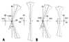
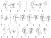
Calculation of the secondary displacement during angular correction (Figs. 2-5)
To achieve realignment of an angular deformity without creating secondary displacement, the axis of correction of angulation (ACA) should be on the CORA.17,18 Whereas the ring fixators allow for versatile hinge placement at any level, a unilateral external fixators have limitations in the placement of the ACA. Therefore, the hinge of a unilateral external fixator could not be placed on the CORA in many cases, and, secondary deformities develop as a result, and should be controlled to achieve the exact realignment.
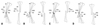
The secondary deformities could be analyzed in two dimensions; lengthening or shortening and medial or lateral translation. There are two simple rules of secondary displacement related to the placement of the ACA. Rule 1 is that, if the ACA is placed on convex side, secondary lengthening deformity occurs, whereas secondary shortening after simple angular correction if on concave side (Fig. 2). Rule 2 is that, if the ACA is not on the transverse bisection line (tBL) of the CORA, the opposite fragment translates to the convex side after angular correction (Fig. 3). The amount of secondary deformities can be calculated simply by trigonometric anaylsis (Figs. 4 and 5).
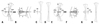
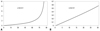
Rate of distraction calculation (Figs. 6, 7 and 8)
Ideal rate for new bone formation by distraction osteogenesis is known as 1 mm/ day.5,6 The slower rates may lead to premature consolidation, whereas the faster rates may result in poor regenerate bone formation. In simple longitudinal lengthening, the rate of distraction is equal at any point of the corticotomy, however, the rate of distraction at any given portion of the corticotomy varies during angular correction. Usually, the gap between corticotomized bone ends is larger on the concave side, therefore, the rate of angular correction should be adjusted so that the rate of distraction of the concave side is closer to 1 mm/day. In cases with passive hinge system, the amount of daily angular correction can easily be calculated by the geometric methods using the rule of similar triangles and the rule of concentric circles, and can be expressed as the amount of daily lengthening of motor system. In passive hinge system, the ACA is fixed on the frame in Ilizarov system or on the convex side of corticotomy in unilateral fixator system, and angular correction is achieved by changing the length of the motor (Ilizarov system) or the lengthener (unilateral fixator) which rotates the passive hinge. However, in active hinge system, angulator directly corrects angular deformity, and the lengthener and translator adjust secondary displacement. Therefore, the rate of angular correction cannot be determined by the simple geometric methods used for passive hinge system.
Regardless of types of fixators, the gap opens larger on the concave side of the deformity after realignment. The rate of angular correction also should be adjusted so that the rate of distraction of concave side is 1 mm/day. Theoretically, after realignment by Dyna-ATC with adjustment of secondary displacement, the convex side of the corticotomy does not change in length, but the cocave side opens to correct angular deformity. The amount of lengthening on the concave side can be calculated with the thickness of the bone at the corticotomy site and the amount of angular deformity (Fig. 6). If the corticotomy is performed on the CORA, no translation deformity happens, however, if not, translation results at the corticotomy site after realignment is achieved. The amount of translation can be calculated with the distance from the CORA to the corticotomy over the longitudinal bisecting line (lBL) (Fig. 6). On the immediate post-operative radiographs, the gap distance of concave side after realignment can be calculated with the expected change in length and translation on the concave side of the corticotomy using the Pythaorean theorem. The rate of angular correction should be given as the amount of daily correction angle, but not as the amount of length change of the fixator. The angular change of angulator determines the secondary change of length and translation of the corticotomy site. The amount of secondary deformity during angular correction can be calculated with the thickness of bone at the corticotomy site, the distance between the ACA and the corticotomy, and tan (a/2) (a is the amount of angular correction) (Fig. 6). The thickness of the bone at the corticotomy site and the distance between the ACA and the corticotomy do not change, once the corticotomy is performed after Dyna-ATC is applied. Therefore, the amount of secondary deformities changes only with tan (a/2) value. If tangent value varies proportionally with changes of angle, the gap distance increases constantly with the given amount of daily correction angle during angular correction. If not, the gap distance varies continuously with changes of the angle, therefore, the amount of correction angle should be readjusted everyday to maintain 1 mm/day of distraction rate on the concave side of the corticotomy. Fortunately, while the value of tangent angle increases exponentially especially over 45 degrees, tangent function curve is nearly straight, less than 30 degrees (Fig. 7). Therefore, in cases with less than 60 degrees of angular deformity, the amount of daily correction angle which permits 1 mm/day of distraction rate on the concave side of the corticotomy can be obtained as the rate of angular correction without daily adjustment during angular correction. Once the amount of daily angular correction is determined, the amount of daily length and translation compensation can also be calculated with the amount of daily angular correction.
Exact adjustment of secondary changes in length and translation at each angular correction opens the concave side of the corticotomy 1 mm per day, but allows minimal gap on the corticotomy of convex side especially in the early stage of angular correction. Therefore, it is possible that the corticotomized bone ends of convex side, may abut each other and prevent angular correction or adjustment of secondary translation. For the cases where the concomitant lengthening is required, longitudinal lengthening prior to angular correction is recommended. Otherwise, about 5 mm pre-lengthening and re-shortening after angular correction could be helpful in avoiding abutment on the convex side of the corticotomy site. Inappropriate sequence of angular correction and adjustment of secondary deformities could be one of the causes of the impingement. Appropriate sequence of correction is lengthening-translation-angulation with Dyna-ATC on the concave side and angulation-translation-shortening with Dyna-ATC on the convex side.
Patients
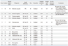
From 2007 to 2008, 13 patients underwent deformity corrections for lower limb angular deformities using Dyna-ATC (Table 1). There were 7 males and 6 females. The mean age at surgery was 17.5 years ranging from 7 to 64. Pre-operative diagnoses were pyogenic arthritis sequelae in 3 patients, Blount's disease in 2, adolescent tibia vara in 2, partial growth arrest after epiphyseal fracture in 2, and DDH, osteosarcoma, hemophilia and malunitedtibial fracture for each one of patients. Two patients had distal femoral varus deformity with shortening, and 3 had distal femoral valgus with shortening. One patient with DDH had distal femoral valgus deformity with shortening and ipsilateral proximal tibia valga. Six patients had proximal tibia vara, two of those had tibial deformities on both sides. One patient with septic hip sequelae had no angular deformity on distal femur, however, varus angulation and lengthening were performed on distal femur as a part of pelvic support femoral reconstruction surgery. Due to the limitation in transverse deformity correction, the patients with rotational limb deformity were not subjected to deformity correction using Dyna-ATC. All patients in this study had normal range of rotational profile in the involved limb. Total 7 femora and 9 tibiae of 13 patients were included in this study. Gradual correction with concomitant lengthening was performed on all 7 femora. Gradual correction without lengthening was performed on 6 tibiae and acute correction in the operating room in 3. For deformity correction of femur, standard type Dyna-ATC and for tibia, T-type were used. Corticotomy was performed using small diameter drill and osteotome. Fibula osteotomy was not combined in the case series of this study. Prophylactic fasciotomy on the anterior compartment was performed on all cases with tibialcorticotomy. Knee range of motion exercise was encouraged the 3rd post-operative day if tolerable. In cases with gradual correction, the latency period ranged from 5 to 7 days according to the age of patients. The rate of angular correction was calculated on the immediate anteroposterior radiograph. Partial weight bearing with crutches was allowed at the 5th postoperative day. During angular correction, anteroposterior and lateral radiographs were taken weekly to evaluate the regenerate new bone formation and deformity correction. Full weight bearing was allowed at the end of distraction period to promote the consolidation of callus. Dyna-ATC was removed after complete corticalization of callus on more than three cortices confirmed on anteroposterior and lateral radiographs.
In cases of acute correction, Dyna-ATC was applied first, and then deformity correction was achieved by osteotomy and manipulation of Dyna-ATC. Secondary change in length and translation was calculated on the fluoroscopic image. Even in cases of acute correction, whole angular correction was not performed at one time to avoid overstretching the osteotomy site and soft tissue, including neurovascular structures, due to secondary displacement. Instead, angular correction was divided into several times with the amount which was determined by the calculation method for the rate of angular correction and compensation of secondary displacement was combined at each time of angular correction. Whole realignment was achieved by repeating angular correction and secondary displacement compensation in the operating room. Partial weight bearing was permitted on the 5th postoperative day. Radiographs were taken biweekly, and ambulation without crutches was allowed if the callus formation at the corticotomy was shown. Clamps of Dyna-ATC were loosened when the maturation of callus was noted on follow up radiographs, and the fixator was removed a week later if there was no clinical or radiographic evidence of collapse or angulation. Average duration of follow up was 32.5 months ranging from 24 to 38. To evaluate the angular deformity, mechanical axis deviation (MAD), mechanical lateral distal femoral angle (mLDFA) and medial proximal tibial angle (MPTA) were measured on pre and postoperative standing teleradiographs. Comparisons were made between pre- and post-op values of MAD, the mean deviation from the normal mLDFA and MPTA, and knee range of motion using paired t-test. Statistical significance was set at p<0.05.
RESULTS
All but one patient had bony healing without additional procedures. The patient who had undergone autogenous pasteurized bone graft due to osteosarcoma on femoral diaphysis showed insufficient new bone formation during distraction and required several additional procedures to achieve bony healing.
In 9 cases with tibial deformities, the average amount of angular correction was 11.0 degrees, ranging from 5.7 to 26.0, and the mean external fixation time was 2.9 months, ranging from 2.4 to 4.2. In 7 cases which underwent angular correction with concomitant lengthening on the femur, the average amount of angular correction and length gain were 10.0 degrees and 6.4 cm, respectively, and the mean time spent with Dyna-ATC was 6.9 months. The healing index averaged to 1.1 mo/cm.
The mean MAD was improved from 31.9 mm to 3.0 mm postoperatively (p=0.001). The mean deviation from normal of the mLDFA in the patients with femoral deformitiy decreased from 11.1 degrees to 1.0 (p=0.014), and that of the MPTA in the patients with tibial deformity decreased from 9.8 degrees to 1.6 (p=0.007). The average pre- and post-operative range of knee motion were 131.9 and 126.9 degrees, respectively, and there was no significant difference (p=0.204).
Almost all patients suffered pin site problems during external fixation. The most common problematic screws were the most distal screw in femoral application and proximal posterior screw in tibia. All pin site problems were grade I or II, and all but one could be controlled by daily dressing and intermittent oral antibiotics medication. One patient required admission for intravenous antibiotics for 1 week. In one patient with septic hip sequela who required 8.5 cm of femoral lengthening, knee joint extension contracture developed during lengthening. Quadricepsplasty was performed at the time of fixator removal and the range of knee motion was restored at the latest follow up. One patient who had underwent autogenous pasteurized bone graft due to osteosarcoma on femoral diaphysis showed insufficient new bone formation during distraction. Bone marrow injection was performed during distraction and demineralized bone matrix was engrafted percutaneously after achievement of angular correction and 6 cm of femoral lengthening. At 8.5 months after application of Dyna-ATC, the patient and the parents were eager to remove the fixator, therefore, the external fixation was converted to internal fixation with locked plate. Eventually, bony healing was achieved at the latest follow up. Overall, there were 16 problems and 4 obstacles in 16 procedures.19 All problems were related to pin tract infection and 4 obstacles were occurred in two patients. No permanent complication developed.
Case presentation
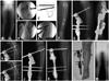
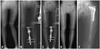
Case 1 (Fig. 8)
The patient was a 7-year-old boy with Blount's disease. He had bilateral involvement and underwent temporary hemiepiphysiodesis and epiphysiolysis on the proximal tibia on the left side two years ago. Although there was no progression of deformity, proximal tibia vara did not improve for two years after surgery. Angular correction using Dyna-ATC was planned. The preoperative MPTA was 71 degrees and MAD was 32 mm. Intraoperative valgus stress arthrogram revealed mild dye pooling on medial side, therefore, medial joint line elevation procedure was not indicated for this case. T-type Dyna-ATC was applied with four screws on the left tibia. Oblique type corticotomy was performed just below the tibial tuberosity, and prophylactic fasciotomy was added on the anterior compartment. Fibula was left intact. The duration and rate of angular correction were determined on immediate post-operative radiograph. After 5 days of latency period, angular correction commenced. Three months later, Dyna-ATC was removed after the consolidation of callus on the corticotomy was confirmed on follow up radiographs. The postoperative MPTA was 88 degrees and MAD was 0. He experienced no complication except mild superficial pin tract infection which was controlled by daily dressing and intermittent oral antibiotics medication. He had full range of knee motion and the parents were fully satisfied with the clinical result.
Case 2 (Fig. 9)
The patient was a 15-year-old girl with bilateral DDH. She had undergone several surgeries, however, left hip was still subluxated and genu valgum with shortening developed on left lower extremity. Preoperative MAD was 72 mm. The mLDFA and MPTA were 76 and 100 degrees, respectively. The femur was shortened by 5 cm and tibia was longer by 2.5 cm on the left side. Gradual angular correction with concomitant lengthening using Standard-type Dyna-ATC on the femur, and acute correction and shortening by medial closed wedge osteotomy and application of T-type Dyna-ATC on the tibia were planned. After 6.4 months of external fixation, Dyna-ATCs were removed. The postoperative mLDFA and MPTA were 86 and 87 degrees, respectively, and the MAD was improved to 2 mm. The femoral length gain was 3.5 cm and tibia was shortened by 1 cm. Although knee joint line was higher by 1.5 cm on left side, overall leg lengths of both lower extremities were equalized. At the time of removal of external fixators, Chiari osteotomy was performed and 5 months later, neck lengthening osteotomy with greater trochanter transfer was added for hip reconstruction.
DISCUSSION
The purpose of this study is to introduce the methods required for the angular deformity correction using Dyna-ATC and to evaluate the clinical outcome of angular correction using Dyna-ATC.
The ACA, CORA, and secondary displacement are not new concepts when the ACA is not on the CORA.17,18,20 Many previous studies adequately described the reasons of why the secondary displacement develops and how to avoid creating the secondary deformities. They also provided the methods to calculate the rate of angular correction. These methods are reasonable because they are based on a simple mathematic calculation, and many surgeons reported successful angular deformity correction using these methods.1,2,6,9,17,18 However, these methods are for ring fixtors with passive hinge system where the versatile hinge placement is possible and lengthening of motor system rotates hinge to achieve angular correction. To avoid creating secondary deformities, they recommend to place the hinge on the tBL of the CORA, and the rate of angular correction is determined by the ratio of the distance between the ACA and the corticotomy to the distance between the ACA and the motor system. These methods are not applicable to Dyna-ATC which is a unilateral external fixator with active hinge system. In most cases, Dyna-ATC does not allow for the placement of hinge on the tBL of the CORA and angulator rotates to correct angular deformity. The secondary displacement develops as a result, which should be compensated during daily angular correction. Therefore, we designed a new calculation method suitable for the unilateral fixator with active hinge system. This method shares the basic concepts with previous calculation methods and is designed based on the simple mathematical calculations. In this study, all but one case which had undergone pasteurized autogenous bone graft surgery on the corticotomy site achieved the desired angular correction and length gain using Dyna-ATC and the calculation method we proposed. The results of this study support clinical usefulness of Dyna-ATC and our calculation method for angular deformity correction.
We acknowledge several limitations of this study. First, number of cases in this study is small and the majority of patients were children and adolescent with angular deformities on the coronal plane around the knee joint. Therefore, the results of this study could not be generalized to the general population who has complex limb deformities except around the knee joint. Second, this study is lack of control group. Unfortunately, we could not find well-matched control groups with various treatment modalities including acute angular correction with osteotomy, gradual correction with traditional Ilizarov ring fixators, and immediate angular correction and limb lengthening with a unilateral fixator. However, the vast majority of the similar studies to ours in the literature also experienced difficulties in finding control groups and reported their results without control groups.11,14-16,21-23 Although we could not compare our results to those of control groups, the study population and the treatment results were comparable to those of previous studies and we found significant improvement of limb deformity after the index procedure in this study. Third, in this study, we could achieve successful angular correction of proximal tibial angular deformity without fibula osteotomy. However, fibula osteotomy might be required in cases of severe angular deformity and/or angular deformity with concomitant lengthening needed. One of the disadvantages of unilateral fixator over ring fixator is inability to fix the fibula fragments to the fixator. Recently, we started to use proximal and distal tibio-fibula screw fixation method proposed earlier by Paley.21 Further study is needed to determine the clinical usefulness of this method.
Ilizarov ring fixator takes several advantages over a unilateral fixator. Ilizarov ring fixator affords versatile hinge placement, flexible screw or wire placement, thus, correction of more complex three plane deformity.5,6,9-11 The disadvantages of Ilizarov ring fixator are the technical demanding of proper hinge placement for surgeons and inconvenience for patients due to bulky frame. Recently, Taylor spatial frame introduced a new correction mechanism using hexapod system instead of hinge motor system and alleviated surgeon's toil over complex calculations and strenuous proper hinge placement during surgery.22,23 However, Taylor spatial frame is still an inconvenient bulky ring fixator for patients. Dyna-ATC is basically a unilateral fixator. It is easy to apply and less cumbersome for patients than bulky ring fixators. Angulator can correct uniplane angular deformities up to 30 degrees. Translator and lengthener can compensate for secondary deformities during angular correction. Daily amount of correction can be determined by the simple calculation method. Although Dyna-ATC still cannot afford the correction of more complex sagittal and transverse plane limb deformities, it could be a useful alternative to bulky cumbersome ring fixators for selective patients with uniplane angular deformities.
In conclusion, this study demonstrated successful outcome of limb deformity correction using Dyna-ATC. We believe that Dyna-ATC is a useful external fixator for limb deformity correction in selective patients group such as angular deformites less than 30 degrees in the coronal plane around the knee joint.
 XML Download