INTRODUCTION
Cervical corpectomy with vertical strut grafting and plating is a common surgical technique for treating degenerative and traumatic conditions of the cervical spine. The graft acts as an axial load-bearing strut, while providing a substructure for bony ingrowth and biological bonding and integration during the fusion process.1,2 An ideal ventral plating system not only minimizes the chance of strut graft extrusion, but also provides immobility and helps to maintain alignment.3-9 However, complications such as graft collapse, graft extrusion, graft subsidence with endplate fracture, pseudoarthrosis, and failure of fusion may occur after surgery.4,10,11 There are many factors that may contribute to the development of these complications, such as implant failure, implant-bone interface failure, and bone-bone interface failure. The majority of the applied axial loads stress the point of contact between the vertebral body and the bone graft. Therefore, the interface between the bone graft and the vertebral body is associated with a greater risk of failure.
The ventral approach to the cervical spine is often complicated by the subsidence of interbody grafts into the vertebral bodies. This process involves a combination of the pistoning of the strut into the vertebral bodies, the collapse of the graft itself, and angular deformation of the cervical lordosis. A sub-optimal "fit" between the bone graft and the vertebra, which is a common technical error, also contributes to the problem. Subsidence is usually exaggerated by an inadequate weight bearing capacity of the bone graft, vertebral body, and implanted device. Overall, it is the axial load resisting ability of the graft, both endplates, and the vertebral implant that affects the fusion process in the postoperative period. Theoretically, a stronger construct can be achieved when the cortical portion of a graft is positioned in line with the ventral vertebral body cortical surface, thereby using the cortical vertebral margins to help buttress axial loads via taking advantages of the boundary effect.12,13
The DOC ventral cervical stabilization system (DOC VCSS; Depuy-Acromed, Raynham, Massachusetts) is one of several dynamic cervical devices that permits and controls subsidence by allowing the movement of a rostral platform along the vertical axis, or rather, the axis defined by the curvature of the spine and the implant.3 This implant also has a unique fin-platform design that is based in part on the theory of the boundary effect. The fin components of the DOC system take advantage of the axial load-bearing ability of the dense cortical margin along the periphery of the vertebral body. Although this implant can be used to allow controlled subsidence (also known as controlled dynamism), it should also buttress axial loads when necessary. Nevertheless, the biomechanical efficacy of the DOC VCSS remains unclear. There are no published biomechanical data authenticating the clinical value of fins. Therefore, this study was designed to examine the biomechanical contributions and load-bearing capacity of the fin components of the DOC VCSS.
MATERIALS AND METHODS
Specimen preparation
Eighteen fresh cadaveric upper thoracic vertebrae (T1-T3) were obtained for this study. The vertebral bodies were disarticulated and cleaned of all soft tissue. The vertebral endplates to be studied were meticulously cleaned of all disc material. The spines had a mean age of 60 ± 6 years. Bone mineral density (BMD) data, determined via dual energy x-ray absorptiometry (DEXA; Hologic QDR 4500A, Waltham, MA), was available for 13 of the vertebral bodies. The mean BMD for these specimens was 0.66 ± 0.16g/cm2. Each segment was embedded in a polyester resin for use in customized gripping fixtures designed for the materials testing system. Specimens were kept moist with saline soaked gauze until the time of testing.
Specimen instrumentation
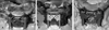
Each specimen was instrumented with a DOC VCSS that was 51 mm in length. Twenty-degree screw trajectory platforms were utilized. This size proved optimal for the instrumentation of the thoracic vertebrae. The ratio of fin area to vertebral body cross-sectional area was calculated. This ratio was maintained for use on the upper thoracic vertebrae, so that a truly clinical comparison of the buttressing effect of the fins on the cortical margin of the vertebral bodies could be made. Three test conditions were devised to quantify the strength contributed by the fins at the endplate (Fig. 1A-C). Each specimen was instrumented using a method randomly selected from three techniques:
Condition A: The rostral platform was placed with the fins resting against the superior endplate. Bone screws were not inserted.
Condition B: The rostral platform without fins was placed on the vertebral bodies, and bone screws (14 mm in length) were inserted. (The fins of each platform were completely removed using an electric saw).
Condition C: The rostral platform was placed with the fins resting against the superior endplate. Bone screws (14 mm in length) were then inserted.
To facilitate the testing of these three conditions, the DOC assembly was modified by inverting the superior platform on the rods. This permitted the fins to rest securely against the endplate and permitted appropriate screw trajectory (20° caudal angulation). The platform was allowed to slide freely along the bilateral rods constituting the DOC assembly during loading applications. The insertional torques were measured for the last three to four screw turns using a torque wrench calibrated to ± 3% (Sturtevant Richmont, Franklin, IL). The caudal platform and cross connector were fixed with locking screws to a distal portion of the implant to prevent the rods from rotating. In conditions B and C, each plating system was fixed with two anchor screws (14 mm in length). A construct securing pin was used to properly position the platform on the vertebral body while the screws were inserted. For condition A specimens, construct securing pins were used to ensure that the platform fins were properly positioned against the vertebral endplate until the specimen was embedded into the gripping fixture. The caudal region of each specimen was secured in a polyester resin (Bondo/Mar-Hyde Corp., Atlanta, GA) in such a manner so that the rostral disc surface was horizontal. Specimens were embedded to their inferior endplates, and the embedding material was permitted to infiltrate the canal and to engulf the dorsal elements and the lower portion of the DOC assembly. This maintained vertebral body alignment, and secured the implant against the specimen in order for a load to be applied to the movable platform only. The ventral surface of the vertebral body was kept free of the embedding material to allow the upper platform to travel during testing.
Biomechanical testing
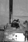
The instrumented vertebral bodies were tested on an MTS materials testing machine (MTS Alliance RT/10, MTS Corp., Eden Prairie, MN). A probe descending from the load cell applied a pure axial compressive load to the superior platform of the DOC construct (Fig. 2). Testing was conducted at a rate of 20 mm/min using displacement control, and data were sampled at a rate of 20 Hz using Testworks 4 software (MTS Corp., Eden Prairie, MN). Compression continued until the DOC platform traveled towards the inferior endplate of the vertebral body, up to a maximum of 10 mm travel. The stiffness of the construct was determined based on the initial linear data from the load-displacement curves. Due to the discontinuous yielding seen during compressive tests to assess the failure at bone-implant interfaces such as this, the 0.2% offset yield was used to determine the yield load (yield strength) of the construct.
Statistical analysis
A one-way analysis of variance (ANOVA) with a Newman-Keuls multiple comparison test was used to detect differences in stiffness and yield strength between the three conditions. Pearson correlations were calculated to determine the relationships between BMD and stiffness, and between BMD and yield strength. All statistical tests were performed using Graphpad Prism 3.02 (Graphpad Software Inc., San Diego, CA). Significance was defined as p < 0.05.
RESULTS
Stiffness
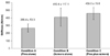
The mean stiffnesses (±standard deviation) are shown in Fig. 3. The condition C specimens (fins plus screws) had the greatest stiffness, at 459 ± 80 N/mm, while the condition A specimens (fins alone) were the least stiff, at 266 ± 53 N/mm. This represented a 42% decrease in stiffness, as compared to condition C. The condition B specimens (screws alone) were 11% less stiff than the condition C specimens (410±117 N/mm). One-way ANOVA with a Newman-Keuls analysis indicated that the condition A specimens were significantly less stiff than those subjected to conditions B and C (p < 0.05). No significant difference was observed between conditions B and C (p > 0.05). A Pearson correlation indicated that there was no statistically significant correlation between stiffness and BMD (p > 0.05).
Yield loads
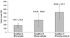
The mean yield loads (±standard deviation) are shown in Fig. 4. Once again, the condition C specimens had superior performance, and had the greatest yield load, 526±168 N. The condition A specimens had the smallest yield loads, 180±54 N, which represented a 66% decrease compared to the condition C specimens. The condition B specimens had 40% smaller yield loads than the condition C specimens (317 ±165 N). A one-way ANOVA with a Newman-Keuls analysis indicated that the condition C specimens had significantly greater yield loads compared to those subjected to conditions A and B (p < 0.05). No significant difference was noted between conditions A and B (p > 0.05). A Pearson correlation indicated that there was no statistically significant correlation between yield load and BMD (p > 0.05). The yield load of condition A plus that of condition B was approximately equal to that of condition C, with condition A contributing about one-third and condition B contributing two-thirds of the overall load-bearing capacity.
DISCUSSION
Many factors affect graft subsidence after surgery. These include the closeness of fit of the bone graft in the vertebral body mortise, the surface area of contact between the bone graft and vertebral body, and the quality of the contact surfaces.12 Historically, the literature has emphasized the importance of the contact surface between the graft and the vertebral endplate.1,12,14,15 The ventral vertebral body cortex can provide a significant advantage as a buttress. It is capable of bearing axial loads much more effectively than softer cancellous bone.16-19 The centrum of the vertebral endplate is significantly thinner and weaker than its periphery, thus increasing the risk of subsidence and fracture through the central portion of the endplate.15,20-22 In 1998, Wang et al. concluded that a greater construct strength is achieved when the cortical portion of a graft is positioned in line with the ventral cortical surface.13 Theoretically, an even more favorable situation exists when the bone graft has nearly the same diameter as the vertebral body, since the bone graft can thus contact the entire cortical margin of the vertebral body in the region of the endplate. However, in clinical situations, fashioning a bone graft with a diameter similar to that of the vertebral body can be challenging.
There are also several experimental studies that support the importance of the contribution of the cortical shell to the vertebral strength. Faulkner et al. estimated that the cortical shell contributed 12% of the total vertebral strength in healthy individuals and 56% in osteoporotic ones.20 Burr et al. concluded from a parametric finite element study that the shell carries approximately 50% of the vertebral force in a young, healthy spine, and approximately 90% in a spine with advanced osteoporosis.23 Rockoff et al. concluded that the cortical shell accounts for 45-75% of vertebral strength, and that a greater portion of axial loads are transferred via the cortical shell in older individuals compared to young ones.24 Yoganadan et al. also concluded that the cortical shell accounts for approximately 40% of vertebral strength.25
Based on this information, the use of the vertebral body margins to buttress an axial load takes advantage of the strength of the cortical shell and the boundary effect. The boundary effect is herein defined as the enhanced buttressing of an axial load provided by supporting the load at the edge of an inhomogeneous vertebral body that is denser at its periphery.1 The fin components of DOC VCSS were designed to enhance the axial load-bearing ability of the construct based on this concept. The fins need only pass beyond the cortical edges of the vertebral body in the region of the endplate to provide an advantage for axial load bearing.
The condition C specimens (fins and screws) yielded the greatest stiffness, whereas the condition A specimens (fins alone) showed the least stiffness. Statistically, the condition A specimens showed significantly lower stiffnesses compared to those subjected to conditions B and C. However, no statistically significant difference was found between condition B and condition C. This finding suggests that construct stiffness is predominantly affected by screw insertion itself more than by the fin components. In the model used herein, the fins were simply resting against the superior endplate, and did not penetrate through the endplate. Moreover, there was no bone graft placed against the fin. This is one of the limitations of the model employed, because the fin was originally designed to be positioned between the cortical margin of the endplate and the bone graft. If a bone graft is used, and the fins are positioned properly between the bone graft and the endplate, the results might be altered. Although no statistically significant difference was observed between conditions B and C regarding stiffness, the condition C specimens were 11% stiffer than the condition B specimens. This suggests that a somewhat favorable result might be obtained in a clinical situation or under other experimental conditions.
The condition C (fins and screws) specimens showed the greatest yield loads. This was followed by condition B (screws alone) and then condition A (fins alone). The yield strength of the specimens employing both fins and screws is roughly equal to the sum of the yield strengths of the specimens employing screws (condition B) and the specimens employing fins (condition A). In contrast to the stiffness results, the condition C specimens showed significantly greater yield loads compared to condition A and condition B. The condition C specimens had 40% larger yield loads compared to the condition B specimens. This result indicates that yield load is mainly affected by the screw component, rather than the fins. Also, this result showed that the addition of the fin components to the DOC ventral cervical plating system provides an augmentation of the axial load-bearing capacity of the construct. In fact, the axial load-bearing capacity (i.e. yield load) effect of the screws and fins appears to be additive, with the screws contributing approximately two-thirds and the fins contributing one-third of the overall capacity.
In this study, upper thoracic vertebral bodies were tested instead of cervical vertebral bodies due to specimen availability. The magnitudes of the parameters measured in the current study may therefore have differed if cervical spines were tested. However, the trends observed in this study are not expected to differ from the trends that may be revealed in the testing of cervical levels.
In the current study, specimens to which platforms were attached using screws alone had approximately twice the stiffness of those using fins alone. The specimens with both fins and screws had nearly twice the yield load of the specimens with screws alone. This study demonstrated that the addition of fins significantly increased the construct stability (axial load-bearing stability) by approximately 34%. The screws contributed two-thirds of the overall axial load-bearing capacity, and the fins contributed the remaining one-third towards this stability. The addition of fins provided a buttress effect against the cortical margin of the vertebral body in an additive manner to that provided by screws, thus augmenting the stability of the construct.