Abstract
With advances in implant technology, total ankle arthroplasty (TAA) has become an increasingly popular alternative to arthrodesis for the management of end-stage ankle arthritis. However, reports in the literature do not focus on the imaging features of TAA. Through a literature review, we demonstrate basic design features of the current ankle arthroplasty system, and the normal and abnormal postoperative imaging features associated with such devices. Pre- and postoperative evaluations of ankle arthroplasty mainly include radiography; in addition, computed tomography and magnetic resonance imaging provide further characterization of imaging abnormalities. Familiarization with multimodal imaging features of frequent procedural complications at various postoperative intervals is important in radiological practice.
The incidence of end-stage arthritis that require more invasive surgical approaches is obviously lower in the ankle joint than in the hip or knee joint (1). Nonetheless, its effect on patient quality of life is substantial. Various treatment options are available for ankle arthritis. Total ankle arthroplasty (TAA) is an effective alternative to ankle arthrodesis, with the benefit of equal pain relief, preservation of joint motion, and possibly improved function (1234). Most published reports on the evolution of TAA focus on the clinical outcomes in relation to surgical findings and management of TAA (15). However, radiographic complications are frequent in patients who have undergone TAA; hence, knowledge of common postoperative imaging features of TAA is important for practicing radiologists (267).
In this article, we briefly review the clinical application and preoperative considerations of TAA, the basic design features of the currently used ankle arthroplasty system, the postoperative imaging modalities with protocol optimization, and the multimodal imaging features of complicated TAA at various postoperative intervals.
Despite the lack of clearly defined specific indications for total arthroplasty by high-quality controlled trials, its indications have gradually expanded. The common indications for TAA include posttraumatic osteoarthritis, primary degenerative osteoarthritis, inflammatory arthritis such as rheumatoid arthritis, hemophilia, and failed prior ankle fusion (3568). The contraindications of TAA are relatively clear, including active soft tissue or bony infection, vascular compromise, severe talar avascular necrosis, peripheral neuroarthropathy, severe sensomotoric dysfunction of the foot and ankle, massive joint laxity (e.g., Marfan disease), and highly compromised periarticular soft tissues (13789). Malalignment and instability of the involved ankle joint require preoperative assessment in order to prevent edge loading, wear, or deformity of the implant that leads to early failure. Patients with severe varus or valgus deformity (> 10°) are also considered inadequate for TAA (57). Some surgeons attempt this procedure after correcting the deformities (e.g., subtalar or triple fusions, and calcaneal osteotomies) (3).
Effective postoperative imaging evaluation of TAA requires awareness of the basic component design and familiarity with the unique features of the various devices in use (2). The first generation of TAA is composed of two parts, namely a concave polyethylene tibial component and a convex metal talar component (3). Regardless of constrained or unconstrained designs of TAA, the outcomes are poor. The first-generation implants require fixing with cement and a large space for the components, hence, extensive bone resection is necessary, resulting in loosening of the devices (17). Discontinuation of the use of these devices due to unacceptably high complication rates, was followed by the introduction of second-generation implants (Agility and INBONE, Eclipse) (Fig. 1A, B) (123). These are also composed of a two-part system, including a polyethylene-bearing surface combined with the talar or tibial component (38). One of the advantages of the second-generation devices is that cement is not used, thereby requiring only minimal bone resection (3). Porous coatings can precipitate bone ingrowth as well (7). The third-generation designs have a third independent polyethylene component, the mobile-bearing meniscus, which is minimally constrained (Fig. 1C-F) (137). Currently, the three-component prostheses with cementless fixation are the gold standard (3).
Understanding of normal imaging features and abnormal findings is imperative in the postoperative radiological evaluation of TAA. While clinical examination is essential to postoperative evaluation, imaging is more useful for early detection of postoperative complications that could be clinically overlooked (8). Thus, routine postoperative imaging has an important role in providing basic but valuable information.
Routine postoperative radiography provides valuable information, including the anatomic relationship between osseous structures and implant components, the presence and extent of bone loss or heterotopic bone formation, and objective postoperative range of motion. Radiography is also useful in the evaluation of changes in serial examinations (28).
Ideally, anteroposterior and lateral views of ankle radiography are obtained in the standing patient to secure physiological positioning (Fig. 2). Postoperative imaging after TAA may facilitate the comparative component status, which may suggest signs of component loosening (5). Non-weight-bearing or weight-bearing lateral ankle radiography in maximal plantar and maximal dorsiflexion positions is useful to evaluate postoperative ankle range of motion.
Further imaging, including computed tomography (CT) and magnetic resonance imaging (MRI), may be useful to confirm and detect postoperative complications suspected or not observed on radiography. CT scan has an advantage over radiography in early detection and more accurate quantification of periprosthetic radiolucencies (osteolysis), fracture, subluxation-dislocation, or arthroplasty device abnormality, which may be obscured on radiography by metallic components in both, the tibia and talus after TAA (10). A modified CT scan technique is required to decrease attenuation and streak artifacts of metal devices (28). Several techniques are used to reduce metal artifacts on CT images. The first step is to align the long axis of the tibia parallel to the CT scan table (11). Furthermore, higher tube kilovoltage results in optimal images by reduced imaging noise; however, it reduces subject contrast and increases radiation dose (1112). Gemstone spectral imaging with metal artifact reduction software, fast kV switching between 80 and 140 kV, can be used (Fig. 3). Virtual monoenergetic extrapolation and iterative metal artifact reduction can reduce metal artifacts efficiently (13). In addition, metal artifacts can be reduced by narrow detector collimation with thin-section imaging. Interpolation software and beam hardening correction software are also potentially useful (14).
MRI is superior to CT scan in assessing the surrounding soft tissue envelope. However, susceptibility artifact resulting from the presence of metallic objects can obscure relevant MRI findings. To reduce these artifacts, the long axis of metallic devices should be positioned parallel to the direction of the main magnetic field (12), but this is often not feasible due to the constraint of bore and coil design. Displacement artifact in the readout direction can be reduced with maximization of the readout bandwidth during slice selection. When limited to conventional pulse sequences, fast spin-echo (FSE) pulse sequences are the best way to reduce artifacts. The gradient echo sequence creates much larger artifacts than the FSE sequence. Modifying other adjustable imaging parameters can help to improve image quality and minimize scan time. Such parameters reported to date include maximal receiver bandwidth, small field of view, high-resolution image matrix, thin sections, increased echo train length, and higher gradient strength for small voxel sizes (12). Optimal fat and water separation is achieved with a Dixon-based or short-inversion-time inversion recovery technique and frequency-selective fat suppression should be avoided. Superior artifact reduction is achieved with a three-dimensional multispectral imaging technique such as multi-acquisition with variable resonance image combination (Fig. 4) or slice-encoding metal artifact correction, which mitigate both in plane and through plane distortions (121516).
The use of intravenous contrast agent in the postoperative imaging is highly dependent on radiologists' preferences. Some authors report that it is helpful in characterizing inflammation, infection, and evaluating soft tissue extent, especially for diagnosis of osteomyelitis, septic arthritis, and soft tissue abscess. Consideration must be given to the limitations of frequency selective fat suppression technique, often paired with standard FSE T1-weighted sequence, in patients with metallic implants when intravenous contrast agent is used (17).
Several factors are reported to maximize TAA outcomes; primarily, bone resection should be minimized, especially on the talar side (239). Destruction of the trabecular bone microarchitecture is hardly unavoidable while performing resection of bone in TAA. Large bone resection may disturb adequate load transfer between the tibial metaphysis and tibial component. Optimal load transfer is necessary to resist the forces across the ankle and allow natural load sharing. In addition, excessive bone resection limits the frequency of revision surgery. For these reasons, in terms of bone resection, less is more. Further, maintaining osseous alignment between the tibial and talar components is also important for achieving physiologically optimal load transfer and for minimizing edge loading (9). It is more tolerable in a valgus than in a varus position, but both can cause medial and lateral pain due to impingement and result in further damage in the long term (18). In addition, pathological overload of soft tissue structures such as ligaments, muscles, and tendons can progressively develop in the presence of misalignment (49). Proper ligament balance is important to achieve ideal function of the restored ankle joint with implants (4); or else, ligaments become exposed to excessive forces due to compensatory motion (179). Moreover, generally more than 5° on dorsiflexion and 20° on plantar flexion are required for adequate gait function after TAA (79).
Radiologists should be aware of common complications of TAA that are, when conducting post-procedural radiographic assessment. Further understanding of the unique anatomy and biomechanics of the ankle is clearly needed. Lee et al. (6) report that 62.2% of patients who undergo TAA develop ≥ 1 radiographic complication(s) with the mean time to the first radiographic complication of 74 weeks after surgery. In addition, radiographic findings are significantly correlated with clinical outcomes. Lucency around the arthroplasty (34.0%) is the most common, and other radiographic complications are as follows: hardware subsidence (24.4%), perihardware fracture (11.1%), syndesmotic screw loosening (10.3%), hardware fracture (6.5%), heterotopic ossification (5.7%), increased varus or valgus angulation of the ankle (5.4%), ankle gutter narrowing (5.4%), and syndesmotic nonunion (2.7%, agility total ankle only) (6). Haskell and Mann (19) report that perioperative complications include wound-healing problems, fracture, aseptic loosening (i.e., not caused by infection), tendinitis, component malposition, neuroma (Fig. 5), and bony impingement.
Complications of TAA may be categorized temporally into three groups, including intraoperative, early postoperative, and delayed complications (28). On the other hand, Glazebrook et al. (20) report that the most important feature of a complication of TAA is its severity or the potential impact on the outcome of surgical procedure. It is not useful to simply group complications based on occurrence rate; instead, they propose the following classification system of complications based on failure rate (Table 1). High-grade complications include aseptic loosening (more than 2 mm), periprosthetic osteolysis, deep infection, and implant failure, as these complications cause failure of TAA at a higher than 50% rate. Aseptic loosening may develop due to failure of initial bone in-growth into the prosthesis or inadequate cementing technique in the early phase. Meanwhile, loosening (Fig. 6) of a previously firmly fixed implant may occur as a result of mechanical overload or physiological bone resorption in months or years after implantation (21). Osteolysis (Figs. 7, 8, 9) is the resultant bony destruction caused by foreign body reaction to the polyethylene particulate debris. It is mainly the consequence of poor component alignment and incongruent polyethylene articulation between the tibial and talar components. Revision TAA or alteration to arthrodesis may be required if loosening is derived from extensive osteolysis(22). Despite these concerns, infection following TAA (Fig. 10) and implant failure (Fig. 11) are relatively uncommon complications.
Technical error, subsidence, postoperative bone fracture, and medial impingement are considered intermediate grade due to the < 50% failure rate in cases with such complications (20). Subsidence (Fig. 12) is defined as a change in the vertical position of the tibial or talar component by ≥ 5 mm (23). It is more common in the talar component (24) and is thought to be caused by inadequate bone in-growth or inadequate component support, with resultant failure of initial component stabilization (22). Postoperative bone fractures (Figs. 13, 14) also have a potential risk of failure, although no long-term adverse effects of such fractures are observed (25). Medial impingement (Fig. 15) is one of the common sources of persistent pain and dysfunction after TAA. About 63% of patients reportedly develop bony overgrowth and subsequent impingement, according to relevant outcome studies (26).
Any failure case resulting from intraoperative bone fractures can be fixated during the operation, and aseptic wound healing problem can be managed without revision of the TAA. Thus, these two complications are considered low grade.
Although TAA is increasingly used, failure of this procedure remains a challenge. Kotnis et al. (27) define TAA failure as persistent pain with signs of implant loosening on standing radiography. Radiological signs, including radiolucent lines around the components, or malposition and subsidence of the component indicate implant loosening. The types of procedures for management of failed TAA vary according to whether the affected ankle is infected (Fig. 16). A two stage salvage procedure is performed in the presence of infection. At the first stage, thorough debridement is performed with removal of the components and all nonviable soft tissue and a gentamicin-loaded cement spacer is inserted. Ankle fusion using an Ilizarov frame or transtibial amputation is included in treatment options at the second stage. A one-stage revision is planned when infection is not suspected. The options include a revision TAA or a hindfoot arthrodesis (27).
Over the past few years, TAA has rapidly developed as a better treatment option for severe ankle osteoarthritis due to encouraging clinical outcomes. Imaging plays an essential role in the preoperative planning and evaluation of TAA. The strong positive correlation between radiographic findings and clinical outcomes necessitates knowledge of both normal and abnormal postoperative imaging features of TAA. Additional CT or MRI can be useful to detect and identify postoperative complications that are suspected or not observed on radiographs.
Figures and Tables
Fig. 1
Total ankle arthroplasty devices.
A. Agility (DePuy, Warsaw, IN, USA), semi-constrained, two-component prosthesis. Fusion of distal tibiofibular syndesmosis is desired to stabilize tibial component. B. INBONE (Wright Medical, Arlington, TN, USA), non-constrained, tibial intramedullary modular component that facilitates better fixation in poor tibial bone. C. Salto Talaris (Tornier, Saint Ismier, France), with third-generation cementless meniscal-bearing designs and asymmetric medial and lateral curvatures of talar component that allow inversion and eversion. D. STAR (Waldermar Link, Hamburg, Germany) has two anchorage bars on tibial platform that enhance fixation to tibial bone. E. Mobility (DePuy International, Leeds, UK). Tibial stem and deep sulcus of talar component accommodate matching polyethylene surface, allowing inversion and eversion motions. F. HINTEGRA (Newdeal SA, Lyon, France), unconstrained, three-component system with screw fixation at talar facets and flat tibial cutting (minimize tibial cutting) is not approved by US Food and Drug Administration.

Fig. 2
Normal appearance of total ankle arthroplasty (TAA) as seen on radiography.
Weight-bearing anteroposterior (A) and lateral (B) radiographs of HINTEGRA TAA show normal appearance. Tibial-talar angle (A) and anterior distal tibial angle (B) are within their normal ranges (< 10° and 89 ± 3°, respectively).

Fig. 3
Normal appearance of total ankle arthroplasty (TAA) as seen on computed tomography.
Coronal (A) and sagittal (B) computed tomographic images (140 kVp with rotation time of 0.6 seconds and collimation of 20 mm using gemstone spectral imaging, 2-mm thickness) show normal appearance of Mobility TAA.

Fig. 4
Normal appearance of total ankle arthroplasty (TAA) as seen on magnetic resonance imaging.
Sagittal proton-density-weighted (A) and multi-acquisition with variable resonance image combination inversion recovery (B) magnetic resonance images of INBONE TAA with corresponding ankle lateral radiograph (C).

Fig. 5
45-year-old woman with posterior ankle pain and tibial neuroma.
Axial proton-density-weighted magnetic resonance image shows neuroma of posterior tibial nerve (arrow) with swelling of nerve fascicles. Thickening of overlying flexor retinaculum (arrowhead) is seen.
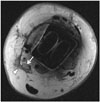
Fig. 6
66-year-old man with loosening around tibial component.
Patient underwent total ankle arthroplasty several years ago and had global ankle pain. Loosening (arrows) is seen on anteroposterior radiograph (A). Coronal multi-acquisition with variable resonance image combination proton-density-weighted magnetic resonance image (B) shows circumferential loosening (arrows) around tibial component.

Fig. 7
66-year-old woman with particle disease with periprosthetic osteolysis and tibial subsidence.
Ankle radiograph (A) and coronal computed tomographic image (B) show cystic soft tissue mass (arrow) communicating with pseudocapsule, and periprosthetic osteolysis (open arrows) around tibial/talar trays with tibial subsidence.

Fig. 8
77-year-old man with periprosthetic osteolysis of talus.
Ankle anteroposterior radiograph (A), and coronal (B) and sagittal (C) computed tomographic images show osteolysis (arrows) at inferior aspect of talar tray.

Fig. 9
82-year-old man with polymeric synovitis and tibial osteolysis.
Sagittal multi-acquisition with variable resonance image combination proton-density-weighted magnetic resonance image shows bulky polymeric synovitis (arrows) with tibial resorption and osteolysis (open arrows).
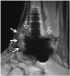
Fig. 10
57-year-old man with chronic osteomyelitis and soft tissue infection.
Sagittal computed tomographic image shows chronic osteomyelitis with antibiotic beads insertion (arrow) at anterior distal tibial metaphysis. Diffuse subcutaneous tissue swelling is also observed.
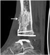
Fig. 11
55-year-old woman with aggravated rheumatoid arthritis and distal syndesmosis instability.
Patient had underlying rheumatoid arthritis. Coronal computed tomographic image shows newly developed multifocal erosions (arrows) at distal tibia and fibula. Distal tibiofibular clear space is widened.
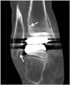
Fig. 12
71-year-old woman with talar subsidence.
Talar subsidence is seen on postoperative ankle anteroposterior radiograph (A). Angular change of more than 5° in measure angle of either component suggests component migration or subsidence. Revision of total ankle arthroplasty is shown, with corrected tibial-talar angle (B).

Fig. 13
51-year-old woman with postoperative lateral malleolar fracture.
Anteroposterior radiograph acquired 4 months after total ankle arthroplasty shows lateral malleolar fracture (arrow).
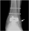
Fig. 14
67-year-old woman with postoperative talar fracture.
Ankle anteroposterior radiograph acquired 5 months after total ankle arthroplasty shows talar fracture (arrows). Reduction and internal fixation for talar fracture was conducted.
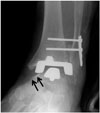
Fig. 15
63-year-old man with medial impingement.
Ankle anteroposterior radiograph shows narrowing of medial gutter caused by bony overgrowth (arrows) at inferior tip of medial malleolus and medial talar neck.
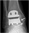
Table 1
Classification of TAA Complications Based on Failure Rate

References
1. Park JS, Mroczek KJ. Total ankle arthroplasty. Bull NYU Hosp Jt Dis. 2011; 69:27–35.
2. Bestic JM, Peterson JJ, DeOrio JK, Bancroft LW, Berquist TH, Kransdorf MJ. Postoperative evaluation of the total ankle arthroplasty. AJR Am J Roentgenol. 2008; 190:1112–1123.
3. Gougoulias NE, Khanna A, Maffulli N. History and evolution in total ankle arthroplasty. Br Med Bull. 2009; 89:111–151.
4. Brunner S, Knupp M, Hintermann B. Total ankle replacement for the valgus unstable osteoarthritic ankle. Tech Foot Ankle Surg. 2010; 9:165–174.
5. Easley ME, Adams SB Jr, Hembree WC, DeOrio JK. Results of total ankle arthroplasty. J Bone Joint Surg Am. 2011; 93:1455–1468.
6. Lee AY, Ha AS, Petscavage JM, Chew FS. Total ankle arthroplasty: a radiographic outcome study. AJR Am J Roentgenol. 2013; 200:1310–1316.
7. Bonasia DE, Dettoni F, Femino JE, Phisitkul P, Germano M, Amendola A. Total ankle replacement: why, when and how? Iowa Orthop J. 2010; 30:119–130.
8. Bestic JM, Bancroft LW, Peterson JJ, Kransdorf MJ. Postoperative imaging of the total ankle arthroplasty. Radiol Clin North Am. 2008; 46:1003–1015. v–vi.
9. Hintermann B. Ankle osteoarthritis: five take-home points regarding total ankle arthroplasty in the rest of the world. In : 26th Annual Summer Meeting of the American Orthopaedic Foot & Ankle Society; 2010 July 7-10; National Harbor, MD USA.
10. Hanna RS, Haddad SL, Lazarus ML. Evaluation of periprosthetic lucency after total ankle arthroplasty: helical CT versus conventional radiography. Foot Ankle Int. 2007; 28:921–926.
11. Kohonen Ia, Koivu H, Vahlberg T, Larjava H, Mattila K. Total ankle arthroplasty: optimizing computed tomography imaging protocol. Skeletal Radiol. 2013; 42:1507–1513.
12. Lee MJ, Kim S, Lee SA, Song HT, Huh YM, Kim DH, et al. Overcoming artifacts from metallic orthopedic implants at high-field-strength MR imaging and multi-detector CT. Radiographics. 2007; 27:791–803.
13. Higashigaito K, Angst F, Runge VM, Alkadhi H, Donati OF. Metal artifact reduction in pelvic computed tomography with hip prostheses: comparison of virtual monoenergetic extrapolations from dual-energy computed tomography and an iterative metal artifact reduction algorithm in a phantom study. Invest Radiol. 2015; 50:828–834.
14. Barrett JF, Keat N. Artifacts in CT: recognition and avoidance. Radiographics. 2004; 24:1679–1691.
15. Hayter CL, Koff MF, Shah P, Koch KM, Miller TT, Potter HG. MRI after arthroplasty: comparison of MAVRIC and conventional fast spin-echo techniques. AJR Am J Roentgenol. 2011; 197:W405–W411.
16. Hargreaves BA, Worters PW, Pauly KB, Pauly JM, Koch KM, Gold GE. Metal-induced artifacts in MRI. AJR Am J Roentgenol. 2011; 197:547–555.
17. Sofka CM. Postoperative magnetic resonance imaging of the foot and ankle. J Magn Reson Imaging. 2013; 37:556–565.
18. Jackson MP, Singh D. Total ankle replacement. Curr Orthop. 2003; 17:292–298.
19. Haskell A, Mann RA. Perioperative complication rate of total ankle replacement is reduced by surgeon experience. Foot Ankle Int. 2004; 25:283–289.
20. Glazebrook MA, Arsenault K, Dunbar M. Evidence-based classification of complications in total ankle arthroplasty. Foot Ankle Int. 2009; 30:945–949.
21. DeOrio JK, Parekh SG. Total Ankle Replacement: An Operative Manual. 2014. Philadelphia: Lippincott Williams and Wilkins;2014. p. 116–122.
22. DeOrio JK, Easley ME. Total ankle arthroplasty. Instr Course Lect. 2008; 57:383–413.
23. Kopp FJ, Patel MM, Deland JT, O'Malley MJ. Total ankle arthroplasty with the Agility prosthesis: clinical and radiographic evaluation. Foot Ankle Int. 2006; 27:97–103.
24. Knecht SI, Estin M, Callaghan JJ, Zimmerman MB, Alliman KJ, Alvine FG, et al. The Agility total ankle arthroplasty Seven to sixteen-year follow-up. J Bone Joint Surg Am. 2004; 86-A:1161–1171.
25. Doets HC, Brand R, Nelissen RG. Total ankle arthroplasty in inflammatory joint disease with use of two mobile-bearing designs. J Bone Joint Surg Am. 2006; 88:1272–1284.
26. Spirt AA, Assal M, Hansen ST Jr. Complications and failure after total ankle arthroplasty. J Bone Joint Surg Am. 2004; 86-A:1172–1178.
27. Kotnis R, Pasapula C, Anwar F, Cooke PH, Sharp RJ. The management of failed ankle replacement. J Bone Joint Surg Br. 2006; 88:1039–1047.


 PDF
PDF ePub
ePub Citation
 Print
Print


 XML Download