

 PDF
PDF ePub
ePub Citation
 Print
Print


INTRODUCTION
Magnetic resonance angiography (MRA) provides the non-invasive imaging of vessels without radiation or additional risk of conventional angiography; time-of-flight MRA (TOF-MRA) is widely used for evaluation of the intracranial artery and contrast-enhanced MRA (CE-MRA) is applied for the carotid artery. CE-MRA is also used for the diagnosis and follow-up of intracranial neurovascular disease because of its higher signal-to-noise ratio, shorter acquisition time, larger coverage, and significantly decreased susceptibility artifacts caused by pulsatility and complex flow (1-4). The introduction of high field strength has benefited the CE-MRA technique with a higher signal-to-noise ratio (SNR). Applying parallel imaging also results in high-resolution vascular imaging with relatively little loss of SNR when imaged at 3T. Despite the advantage of a high magnetic field strength system, the problem of increased susceptibility artifacts exists (5).
With the growing use of MRA for non-invasive follow-up evaluation of vascular disease after treatment, stent-related MR artifacts have been reported in various parts of the body (4, 6-14). Vascular signal loss or artificial luminal narrowing (ALN) by carotid stenting on CE-MRA has also been reported (14-17). These reports revealed that a nitinol stent generally creates less artifacts than a stainless steel or cobalt stent (1, 9, 18, 19).
The intracranial nitinol stent is increasingly used to treat intracranial stenosis and for endovascular coiling of aneurysms with the neck remodeling technique when treating the wide neck of an aneurysm (20-23). To our knowledge, however, the effects of the type of small intracranial nitinol stent and MR parameters on CE-MRA have not been comprehensively evaluated. In our in vitro study, we compared in-stent luminal narrowing on CE-MRA with various parameters for different intracranial nitinol stents.
MATERIALS AND METHODS
Phantom Design
Our study was performed in vitro using a static phantom design. Three vessel-like silicon tubes with an inner diameter of 3.2 mm were fixed parallel to each other in a rectangular plastic box. Two intracranial nitinol stents were used: Enterprise® (4.5 mm/28 mm; Codman & Shurtleff, Raynham, MA, USA) and Neuroform® (4.0 mm/20 mm; Boston Scientific, Natick, MA, USA). Each stent was placed in vessel-like silicon tubes filled with a solution of Gd-DTPA (1 L of saline solution with 2 mL of Gadovist® [gadobutrol; 0.5 mol/L; Bayer Schering Pharma AG, Berlin, Germany]). The remaining tube represented the control tube without a stent. This phantom box was filled with normal saline outside of the vessel-like silicon tubes.
MR Imaging
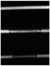
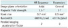
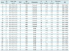
We used 1.5-T (MAGNETOM Avanto; Siemens Medical Solution, Erlangen, Germany) and 3-T (MAGNETOM Verio; Siemens Medical Solution, Erlangen, Germany) MR machines to obtain images. However, images were not obtained by TOF-MRA, but by CE-MRA because of our static phantom design. Because contrast media have very short T1 relaxation times, using a very short TR can cause the inflow effect to be diminished, making the MR signal stronger. We used a T1-weighted 3D spoiled gradient-echo sequence with minimal repetition time (TR) (< 5 ms), minimal echo time (TE) (< 2 ms), and a flip angle of 25° to evaluate the variable MR parameters. CE-MRA (Fig. 1) was repeatedly obtained with the application of the following MR parameters: 1) imaging planes of different orientation (axial versus coronal); 2) voxel sizes (0.7 × 0.7 × 0.7 mm3 versus 0.5 × 0.5 × 0.5 mm3); 3) bandwidths (660 Hz/pixel versus 430 Hz/pixel); 4) magnetic field strengths (3 T versus 1.5 T); and 5) parallel imaging (acceleration factor, 2 versus 0) (Table 1). With the wider bandwidth (640 Hz/pixel) at 3T, CE-MRA with a smaller voxel size could not be performed. Thus a total of 24 MR series for the same phantom was repeatedly obtained, and their parameters were described in Table 2.
Imaging Analysis
The diameter of the stented tube lumen on CE-MRA (D cemra) was automatically measured on a workstation (AQI, Aquarius iNtuition; TeraRecon, Inc., San Mateo, CA, USA) for image processing; measurement was perpendicular to the stent wall for each axial image or axial multiplanar reformatted image when imaged with the coronal plane. D cemra were measured three times for each MR series to reduce intra-observer measurement error.
The reference diameter of the stented tube lumen (D X-ray) was measured using a biplane angiographic system (Axiom Artis; Siemens, Germany). The D X-ray of each stent was calculated based on a radiopaque reference scale that was simultaneously X-ray imaged with the stented tubes. The D X-ray closely approached the real diameter of the stented tube lumen without a stent-related MR artifact.
D X-ray (Enterprise): 3.16 mm
D X-ray (Neuroform): 2.90 mm
For each stent with variable MR parameters, ALN was calculated as: ALN = (1-[D cemra/D X-ray])
Statistical Analysis
A multiple linear regression analysis was used to quantify the influence of MR parameters to ALN. The paired t test (SPSS Inc., Chicago, IL, USA) was used to assess the difference in ALN between the axial and coronal orientation, 1.5 T and 3 T, the 430 and 660 Hz/pixel bandwidths, 0.5 × 0.5 × 0.5 mm3 and 0.7 × 0.7 × 0.7 mm3 voxel sizes, and the 0 and 2 parallel imaging factors. The paired t test was also used to assess the difference in ALN with the same MR parameters between the Enterprise® and Neuroform® stents. The intra-observer reliability of three ALN measurements was evaluated by intraclass correlation coefficient (SPSS Inc., Chicago, IL, USA).
RESULTS
For Neuroform® stent, multiple linear regression analysis showed that 4 magnetic resonance (MR) parameters may influence ALN (Table 3): image plane orientation (p = 0.001), magnetic field strength (p < 0.001), voxel size (p < 0.001), and bandwidth (p < 0.001), R2 = 0.853. For Enterprise® stent, multiple linear regression analysis showed that 3 MR parameters may influence ALN (Table 3): image plane orientation (p < 0.001), magnetic field strength (p < 0.001), and voxel size (p = 0.006) influenced ALN, whereas bandwidth did not (p = 0.057), R2 = 0.931. Applying the parallel imaging factor did not influence ALN for both stents (p = 0.758 for Neuroform®, p = 0.177 for Enterprise®).
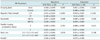
Table 4 shows mean ALN, its standard deviation, and the statistical significance by paired t test between these 5 MR parameters for two stents. ALN was significantly reduced with an axial orientation, lower magnetic field strength (1.5 T), and wider bandwidth (660 Hz/pixel) for both stents. ALN was significantly reduced with a larger voxel size (0.7 × 0.7 × 0.7 mm3) for Neuroform® stents (paired t test), but not for Enterprise® stents.
In the comparison of the two stent types, the Neuroform® stent showed the lower ALN (0.060 ± 0.058) than the Enterprise® stent (0.070 ± 0.058), but the difference was not statistically significant (p = 0.077, paired t test).
Internal consistency was excellent (Intraclass correlation coefficient = 0.949, p < 0.001) for the three repeated ALN measurements of the same stent under the same conditions.
DISCUSSION
We applied variable MR parameters to investigate which conditions provided the better visibility of lumens with the relative small diameter of intracranial nitinol stent on CE-MRA. Additionally, in-stent ALN was influenced by image plane, magnetic field strength and voxel size for both Neuroform® and Enterprise® stents.
A magnetic susceptibility artifact is a type of stent-induced artifact and is caused by local distortions in the magnetic field when two tissues with different magnetic susceptibilities are juxtaposed (24). A well-known theory is that the use of a small voxel, short TE, short TR, wide sampling bandwidth, and parallel imaging will help reduce the magnetic susceptibility artifact (24-26). The stented lumen is also hindered by the radiofrequency artifact as well as the magnetic susceptibility artifact on MRA. Because the magnetic susceptibility artifact from a stent can be minimized using short TE sequences, and the shortest possible TE can be achieved using the widest bandwidth (18), we applied the shortest possible TE and TR for each CE-MRA in our study of vascular phantoms.
A radiofrequency artifact or Faraday cage effect reduces the penetration of radiofrequency into the stent, decreasing the effective MR signal within and outside the stent (27). Unlike stainless steel or cobalt alloy stents, nitinol stents are relatively more sensitive to radiofrequency artifacts than to susceptibility artifacts (9). For nitinol stents, the visualization of the stented segment is at least partially overcome by using a higher flip angle (1, 4, 18, 19). However, a limitation exists with respect to the amount of radiofrequency energy that can safely be deposited in the body (specific absorption rate limit), as set by the US Food and Drug Administration. At a very high flip angle, this limitation imposed the need for prolonged TRs to keep the power deposition within safety margins. In our study, we performed CE-MRA sequences with the shortest possible TRs and a fixed flip angle of 25°.
The artifact at the ends of the stents is due to a local magnetic field alteration resulting in a misregistration in the readout direction. This artifact is minimized when the readout gradient direction is kept antiparallel to the direction of the markers (28). When the stented segment is imaged after stent-assisted coiling in humans, the coiled aneurysm is located at the middle of stented segment in most cases. Thus, as in our study, it is better to place the readout gradient direction perpendicular to the direction of the stent, in order to reduce ALN at the midpoint of stented segment.
Bartel et al. (1) reported that applying the wider bandwidth can reduce susceptibility artifact and radiofrequency, at the expense of reduced SNR of the vascular signal intensity on TOF-MRA. On the contrary, wider bandwidth of CE-MRA with intravascular contrast media in our study was effective in reducing ALN with negligible loss of SNR at the stented segment.
Artificial luminal narrowing at 1.5T was significantly lower than ALN at 3.0T in our results. However, Hahnel (9), and Lettau (16, 17) have reported that ALN of the carotid stent at 3T was lower than that at 1.5T. We could not accurately explain the reason for this difference. The use of a smaller intracranial stent with a relatively small strut and application of a fixed flip angle of 25° might be reasons for the different results.
From the evaluation of two nitinol stents in our study, Neuroform® stents showed lower ALN, although the reduction was not statistically significant. A recent clinical study by Choi et al. (4) showed that 3D contrast-enhanced MRA on 3T provides a higher quality view of the stented parent arteries than TOF MRA. In addition, the quality of the arteries which were stented with Neuroform was superior to that of the arteries stented with Enterprise in both TOF and CEMRA. The thickness of strut in the Neuroform® was 0.07 mm, compared to 0.08 mm for the Enterprise®. These two stents are also different in cell design; Neuroform® has an open-cell design and Enterprise® has a closed-cell design. The Neuroform® with thinner stent strut might cause lesser RF shielding artifact, as well as provide better image quality compared with the Enterprise® stent. Of the various MR parameters compared, ALN was lower with larger voxel size (0.7 × 0.7 × 0.7 mm3) for the Neuroform® stent, but not for the Enterprise® stent in our series.
Our static phantom study contains several limitations. First, the absence of flow and pulsatility in our phantom study may reduce comparability with an in vivo situation. Second, we did not evaluate how the visibility of a vessel containing a stent is influenced by the background signal intensity in different tissues. Visibility of a vessel containing a stent is influenced by the background signal intensity in different tissues. The homogeneous liquid surrounding our phantom is not comparable with the physiologic state. Third, the D X-ray is an arbitrary parameter that does not exactly reflect the real diameter of the stents. Although two stents were placed in phantom with same diameter, different size (4.0 mm/20 mm for Neuroform® and 4.5 mm/28 mm for Enterprise® stents), different radial force as well as cell design might have resulted in a difference in the diameter of the stented lumen in the phantom. Thus we measured D X-ray as standard of reference. Fourth, we did not evaluate the Solitaire® stent which has been recently approved for stent-assisted coiling of an intracranial aneurysm. Because this stent has an open-slit design and results in partially overlapped struts when placed in the smaller diameter of the vascular lumen, CE-MRA of this non-uniformly overlapped strut might result in a bias when measuring the ALN from the vascular phantom; thus it was not included in our study. Fifth, we used one phantom, imaged the phantom once for each parameter, and measured diameter three times for each MR data set. Single acquisition for each parameter is too small to generalize the results to other studies. However, in our study, CE-MRAs of one parameter for comparison were repeatedly obtained with various other parameters, resulting in a total of 24 data sets, where were compared statistically for each parameter and stent. Sixth, because the CE-MRA with smaller voxel size was unable to be performed with the wider bandwidth at 3T, the total number of MR data sets evaluated was not 32 but 24.
In conclusion, CE-MRA for stent patency was impaired by ALN. The axial orientation perpendicular to the axis of stent, wider bandwidth, and lower magnetic field strength reduced ALN on CE-MRA for both stents. The Neuroform® stent showed lower ALN, although it was not statistically significant. Larger voxel size showed a lower ALN for Neuroform, but not for the Enterprise® stent. The results of this study suggest that radiologists can minimize ALN by adjusting the MR parameters.

 XML Download