

 PDF
PDF ePub
ePub Citation
 Print
Print


During the past three decades, breast cancer has been the leading cause of death for American women aged 35 to 54 (1). The basis concept of a mammography is to detect breast cancer by identifying tumor masses and microcalcifications. Although various modalities include MRI (2), ultrasound (3), scintimammography, thermography, and electrical impedance imaging have been used for detecting breast cancer, screen-film mammography and full-field digital mammography are the only imaging tools explicitly approved or grandfathered for breast cancer screening by the US Food and Drug Administration (4).
Conventional screen-film mammography has been widely used for breast examinations. Recently, digital mammography has gradually replaced the screen-film system. In digital mammography, the image is taken by pixel-based electronic detectors known as a CCD (charge coupled device) camera or a CMOS (complementary metal oxide semiconductor) detector. Digital mammography has great potential to supersede film-screen mammography because of its superior detection rate, and it can more accurately diagnose breast cancer (5). Digital mammography is now commercially available, and its spatial resolution is approximately 8-11 lp (line pair)/mm at 10% MTF (modulation transfer function) depending on the type of used detector (6).
Inspection of only local breast lesions using mammography is required for the second-step examination. For conventional projection-type mammography, the whole breast sustains a radiation dose even if the area of interest is only in the local field. Local examination with low radiation dose is possible when a parallel beam is used rather than a divergent beam. The parallel beam can be generated by parabolic polycapillary optics combined with an X-ray tube. Parabolic polycapillary optics (10) is composed of tens of thousands of parabolic glass capillaries with channel diameters ranging from 2 to 12 µm (11). X-rays generated from the spot of the X-ray tube propagate each parabolic capillary. The X-rays are reflected on the inner surface of each parabolic capillary and then finally transforms to a parallel beam by the parabolic shape of each glass capillary. In previous studies (7-9), capillary optics, not parabolic polycapillary optics, has been used in mammographic imaging for the purpose of improving image contrast.
In this study, we examined a small-field digital mammographic imaging system that used parabolic polycapillary optics. In particular, we considered spatial resolution and radiation dose for the small-field digital mammographic image system.
MATERIALS AND METHODS
To develop a compact system for basic experiments, we chose a sealed X-ray tube with a molybdenum target (Oxford Instruments Inc., CA). The voltage we could apply ranged from 10 to 50 kVp (voltage-peak), and the maximum current was 1 mA. The beam stability was greater than 98% for run conditions. The focal spot size of the molybdenum target was approximately 100 µm in diameter. We clearly observed strong characteristic radiations of 17.479 keV and 19.608 keV, which corresponded to the Kα and Kβ, respectively, of molybdenum. The Bremsstrahlung broadband spectrum was also generated by bombarding of the target material with electrons.
The X-rays generated from the target were reflected on the inner wall of each capillary and they passed through the parabolic polycapillary optics. As the shape of the each capillary was a parabola, the X-rays radiated from a focus of the parabola passed through each capillary and they were parallel to the optical axis. In other words, the polycapillary optics transferred the divergent X-rays to a parallel beam along the optical axis.
The parabolic polycapillary optics (X-ray Optical Systems, Inc., NY) was coupled with the X-ray source. The outer diameter and length of the parabolic polycapillary optics were 10 mm and 133 mm, respectively. For Mo Kα radiation, the critical angle of each capillary was 1.7 mrad and the reflectivity of a single reflection on the capillary was greater than 0.8. The incidence X-rays with the critical angle were reflected approximately 17 times on the inside wall of each capillary, and in this case, the reflectivity was approximately 0.02. However, when the incidence X-rays with less than the critical angle were included, the final transmission efficiency of the generated X-rays could be as high as 0.3. Taking into consideration the transmission efficiency, the applied tube voltage was 40 kVp which was higher than the applied tube voltage for conventional mammography. In this study, the operating condition of the X-ray tube for imaging test objects was fixed at a tube voltage of 40 kVp and a current of 0.5 mA, and the exposure time to let the image develop was three seconds. The parabolic polycapillary cut the high energy of more than 20 keV by its X-ray reflection properties, but the low energy X-ray of less than 20 keV was passed by the parabolic polycapillary. Thus, a tube voltage more than 40 kVp could be applied and the number of photons generated on the X-ray tube could be increased. In a tube voltage of 40 kVp with a current of 0.5 mA, the number of photons generated by the molybdenum target X-ray tube in front of the polycapillary optics was ~ 6×10⁸ photons/sec. The image contrast was similar to that of conventional mammography. It meant that the number of photons on the detector was enough to make a digital image.
In our experiment, a CCD detector (Princeton Instruments Inc., NJ) with a 24 µm × 24 µm pixel size was used for imaging. We also used a Si-PIN detector (Amptek Inc., MA) to characterize the X-ray spectrum. The effective sensing area of the CCD camera was 50 mm × 50 mm. The Nyquist frequency of the captured image using the CCD detector was 21 lp/mm for which the spatial resolution was limited by the pixel size of the CCD detector. In order to obtain a higher spatial resolution of 21 lp/mm in our system configuration, the pixel size of the CCD detector would have to be less than 24 µm × 24 µm. The CCD chip was cooled down to 223 K to reduce the dark noise of the CCD detector.
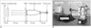
Figure 1 shows the experimental setup used to evaluate the performance of the small-field digital mammography. Parallel X-ray beams by the parabolic polycapillary optics entered a filter and then passed through a test sample. The sample image was finally recorded on the CCD camera. The small-field digital mammography setup was fixed on a optical table. The object stage could move in a vertical direction to the optical axis. Image series for a test sample could be obtained by scanning the object stage. All images used in these experiments were corrected by post-image processing, and the contrast (Imax - Imin) / Imin, was calculated by maximum and minimum pixel values.
The objects on an image are distinguished by their contrast difference and achievable spatial resolution of the system. The MTF of an imaging system shows a performance of the spatial resolution connected with the contrast (12). We directly examined the MTF to verify the spatial resolution of the small-field digital mammographic imaging system by taking images of the line-pairs instead of indirectly obtaining the images from an edge spread function. The exposure time was three seconds when we took the linear pattern images of a phantom of a gold-line. We then evaluated the MTF by using the linear pattern images.
X-ray exposure gives rise to energy accumulation in an object, and the energy can destroy biological tissue and its chemical state. When X-ray photons N with a wavelength λ are irradiated on the area d2 of a sample, then the dose of the specimen with the thickness Δ and density ρ can be written as:
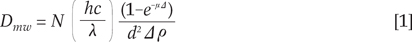
which is the radiation dose for a single X-ray wavelength or energy of hc/λ, and where µ is the linear absorption coefficient of the sample. All the X-rays that arrive on the sample contribute to the radiation dose of the sample. Therefore, the radiation dose D for a general X-ray tube source can be expressed as:

We measured the radiation exposure to enter the test sample using an ionization chamber (Fluke Corp., OH) with an exposure time of three seconds and measured the spectrum of incident X-rays to the test sample together. The absolute number of X-ray photons with energy hc/λ was known by the radiation exposure and the X-ray spectrum, and the radiation dose of the test sample was obtained from equations [1] and [2] and the material information of the test sample. This method is similar to the dose measurement in which X-ray tube voltage and half-value layer (or equivalent other parameters) should be known. The relative uncertainties in the measured radiation dose were within ± 4%.
We obtained an image more than 10 mm in diameter by scanning a test standard phantom of breast and combining each scanned image. Breast tissue which was fixed by paraffin and proven on biopsy to be a ductal carcinoma in situ was imaged with the small-field digital mammographic imaging system. A conventional projection-type digital mammography of the breast tissue sample was taken to compare with the findings of the small-field digital mammographic imaging system. The breast tissue study was carried out in accordance with the regulations of the Institutional Review Board of university.
RESULTS
Spatial Resolution
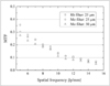
There were various choices of filters for our mammographic imaging system, e.g., molybdenum (Mo) and rhodium (Rh). The spatial resolution of 12 lp/mm for the molybdenum and rhodium filters with a 25 µm thickness was achieved at a MTF of 10% as shown in Figure 2. The image using the rhodium filter is seen in Figure 3. The spatial resolution was one of the highest resolutions achieved from digital mammography. The spatial resolution of 12 lp/mm corresponded to 41.7 µm in spatial resolution. From the standpoint of the CCD detector, this spatial resolution was matched to almost two pixels.
When we used molybdenum filters with 25 µm and 50 µm thickness, the MTF values for each filter weren't very different. However, the contrasts for the molybdenum filter with a 25 µm and 50 µm thick was 1.7 and 1.5, respectively. The contrast was measured with a step-like acrylic object. In the case of a 25-µm molybdenum filter, the contrast for was 12% higher than that for a 50-µm molybdenum filter. The image contrast was proportional to the square of the photon number detected on the CCD camera. Thus, the thick filter led to a lower contrast. When a 100-µm-thick molybdenum filter was used in the mammographic imaging system, the contrast rapidly decreased to 0.48 and the spatial resolution was 11 lp/mm.
Radiation Dose
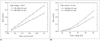
Figure 4 shows the radiation dose using rhodium filters of 25-µm thickness for an acrylic phantom with a 44 mm thickness (Mammographic Accreditation Phantom, CIRS, VA), equivalent to a 42 mm compressed breast with 50% glandular tissue and 50% adipose tissue, as a function of the tube current and fixed voltage for molybdenum. The radiation dose increased as the tube current increased at a fixed tube voltage. The radiation dose, as a function of the voltage at a fixed current, increased quadratically.
The radiation dose shown in the Table 1 is when the parabolic polycapillary optics was not combined with the X-ray tube in our system configuration. When no parabolic polycapillary optics was used, the system became a conventional projection-type digital mammography. The radiation dose of the system without the parabolic polycapillary optics was three times higher than with the parabolic polycapillary optics. The field that was exposed to the radiation dose for the small-field digital mammographic imaging system was 3% of the field for the projection-type system. The small-field digital mammographic imaging system compared to the projection-type digital mammography had advantages in terms of the radiation dose, dose field and absorbed X-ray energy as shown in Table 1. Radiation dose was calculated from the measured X-ray energy absorbed and the measured dose field which led to mass information. In the mammography system without the parabolic polycapillary optics, the field illuminated X-ray could be controlled by lead block or collimator. In this case, the radiation field could be small. However, the radiation dose was still three times higher because the radiation dose was not proportional to the field size but to the accumulated X-ray energy and mass of the object. In our small-field mammographic imaging system, the radiation doses for the molybdenum and the rhodium filters were 0.18 mGy and 0.13 mGy, respectively. Theoretical estimation of the radiation dose (13, 14) for the phantom was 0.32 mGy at a radiation exposure of 0.15 R, a half-value layer of 0.41, and a tube voltage of 35 kVp for a Mo/Rh tube-filter combination. The value of 0.32 mGy was very close to the 0.38 mGy in Table 1. In addition, the American College of Radiology advocates that the maximum value of the mean glandular dose must not exceed 3 mGy (15).
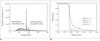
We compared spectra for X-ray beams passing through parabolic polycapillary optics combined with the X-ray tube and direct X-ray beam as shown in Figure 5A. The high energy X-rays larger than 20 keV were almost removed by propagating the parabolic polycapillary optics although low energy X-rays were also reduced simultaneously. The cut-off of the high energy could also be verified by the calculation of the X-ray reflectivity on the inner surface of the parabolic polycapillary optics (16). Figure 5B shows the X-ray reflectivity as a function of X-ray energy at the fixed incidence angle of 1.7 mrad. After two reflections, the high energy X-rays of more than 20 keV were almost removed. The X-ray generated from the X-ray tube could be reflected up to 17 times on the inner surface of the parabolic polycapillary optics. Low energy X-rays have a larger critical angle than that of high energy X-rays, but the reflectivity of the low energy X-rays decrease at a larger incidence angle than its critical angle. Thus, the intensity of low energy X-rays passing through the parabolic polycapillary optics with various incident angles was also reduced as shown in Figure 5A.
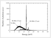
Additionally, the molybdenum and rhodium filters remarkably reduced the low energy of the X-ray beam which passed through the parabolic polycapillary optics removing the high energy larger than 20 keV of the generated X-rays because the critical angles for the high energy X-rays were smaller than that for molybdenum radiation. Because of the parabolic polycapillary optics and the filter, the radiation doses were remarkably reduced, and the fact that the rhodium filter allowed a lower radiation dose could be verified by measuring the energy spectra shown in Figure 6. Within the overall energy region, the number of photons for the rhodium filter was lower than that for the molybdenum filter.
Imaging for Small-Field Digital Mammography System
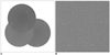
We were able to obtain an enlarged image more than 10 mm in diameter by scanning a test object and combining each scanned image. Each scanned image was overlapped by approximately 30% of the field in order to guarantee that no scan field was missed on the test sample. It took four seconds to take one image to next image. X-ray exposure to make an image was three seconds and the object was moved for next imaging during one second.
Figure 7A presents the scanned and recombined phantom image of 0.32-mm-Al2O3 specks which simulate the microcalcifications of breast cancer. This image consisted of a combination of three scanned images. The 44-mm-thick acrylic phantom contained fibers, specks and masses that were composed of various materials. Figure 7B shows an image of the same specks taken on projection-type digital mammography. The system produced a magnified image of 1.07 X, and the spatial resolution of the system was 11 lp/mm which was tested by a line-pair phantom. The spatial resolution was limited by the spot size of 100 µm rather than the pixel size of the detector because of the cone beam. Comparing both sets of images in Figure 7A, B, the ratio of background noise, which was defined as small-field mammographic imaging system / projection-type digital mammography, was 0.8. It meant that the image contrast of the small-field mammographic imaging system might be 1.2 times higher than that of the projection-type, digital mammography.
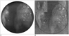
Figure 8A clearly shows microcalcifications within breast tissue which was fixed by paraffin and proven by biopsy to be ductal carcinoma in situ. Multiple calcifications were clearly shown within a field of view. A small figure located on the left upper position in Figure 8B shows a full image of the breast tissue sample taken with a projection-type digital mammography, and the outer black circle in Figure 8B was the same field taken with the small-field scanning mammographic imaging system. Calcifications located within two small circles in Figure 8A were clearly observed. In Figure 8B, it was difficult to distinguish calcifications located at the same positions because of lower image contrast. In addition, a black square in Figure 8A clearly shows two separated microcalcifications. However, the same objects in Figure 8B seemed to one unseparated object. Because of the high spatial resolution of 12 lp/mm for the small-field mammographic imaging system, two microcalcifications could be distinguished. However, the projection-type digital mammography could not distinguish two objects because of the separation distance was at the resolution limit of 11 lp/mm.
DISCUSSION
Previous studies (7-9) have demonstrated the potential for X-ray capillary optics, non-parabolic polycapillary optics, aligned between the object and computed radiography phosphor imaging plate, to be incorporated into digital mammographic image. The capillary optics reduced the scattered X-rays reached on an image plate. Consequently, the post-object capillary optics had the potential to increase image contrast by eliminating scattered X-rays. A scanning process is also required to obtain an image because the size of the capillary optics is small. In the system configuration, the capillary optics played a role as a small 'grid', and there was no improvement on the spatial resolution which was approximately 5 lp/mm because the divergent X-ray source of 100 µm spot size illuminated the object and the pixel size of detector was large. In addition, the system configuration could not avoid a high radiation dose because of long exposure time, i.e., six seconds per one scanned image during scanning. In the scanning process, the capillary optics and the detector were combined with each other and moved together.
We modified the system configuration to improve the spatial resolution and to reduce radiation dose instead of sacrificing the contrast slightly (Fig. 1). The spot size of the X-ray tube used in this system was not an important factor in effecting the spatial resolution due to the use of a parallel beam. For the parallel beam, there was no image blurring by finite spot size of the X-ray tube, and the pixel size of the detector was a critical factor to determine the spatial resolution. The illumination area of the parallel beam was small because the diameter of the parabolic polycapillary optics was small. Therefore, the field of view was limited. However, there was enough space to increase the field of view by scanning the object. When the X-ray tube of 100-µm-spot size without the parabolic polycapillary optics and the same CCD detector are used to make a projection-type X-ray image, we may obtain a similar spatial resolution of 12 lp/mm at a magnification of 1.48. In the imaging system using the divergent X-ray beam, the edge gradient blurring for the spot size and the magnification may correspond with the two pixels of the CCD detector which is almost equal to the spatial resolution. If the magnification is larger than 1.48, the spatial resolution will be worse, and if the magnification is smaller than 1.48, the spatial resolution will not improve because one line-pair needs two pixels to separate the pattern at least. In this sense, only similar spatial resolution of 12 lp/mm will be available at a magnification of less than 1.48 for the divergent X-ray beam. In addition, a high radiation dose compared to the low radiation from small-field digital mammographic imaging system cannot be avoided for the divergent beam.
In general, a thick filter considerably reduces low-energy X-rays including also characteristic radiations and requires a longer exposure time to obtain the same number of photons on the CCD detector compared to a thin filter. With using a thick filter, the detector noise could be increased and the image quality might be reduced if the X-ray source was not strong enough. Spatial resolutions of 12 lp/mm for molybdenum and rhodium filters with a 25-µm thickness were obtained using the small-field digital mammographic imaging system. The resolution in the digital mammographic imaging system strongly depended on the pixel size of the detector. The resolution should be improved in future with advances in the manufacturing technology for CCD or CMOS detectors thereby creating a smaller pixel size.
The radiation dose depended on the filter used. The 25-µm-thick rhodium filter showed a lower radiation dose of 0.13 mGy. The small-field digital mammographic imaging system was able to diminish the radiation dose compared to that of the conventional projection-type mammography, for which an entire object receives the radiation dose. In addition, the parabolic polycapillary optics itself plays a role of a low-pass filter to eliminate X-rays which have higher energy than molybdenum radiation. Image blur and radiation dose by X-ray beams of high energy which are not removed by conventional molybdenum and rhodium filters can be remarkably reduced. The X-ray beams of high energy larger than 20 keV removed contributes to improve image quality and to reduce the radiation dose.
In other applications, e.g., conventional radiography, high energy X-ray, for instance, 75 keV, is required. To propagate the high energy X-ray, each diameter of glass capillary in the polycapillary optics should be very small, i.e., sub-micrometer size, because the critical angle for the high energy X-ray is extremely small. In current manufacturing technology, it is very difficult to make such parabolic polycapillary optics. Thus, general X-ray imaging using parallel beam through the parabolic polycapillary optics can be restricted. In addition, the parabolic polycapillary optics reduces the X-ray intensity. Therefore, to obtain a parallel beam of high photon flux, the X-ray tube should have a high capacity.
In conclusion, due to its high spatial resolution and low radiation dose, a small-field digital mammographic imaging system has the potential to be used for examining local volumes of breast tissue. A relatively large field image can also be examined using the scanning function. This system can be a useful diagnostic tool for examining a small field of breast cancer with a low radiation dose to the patient after conducting conventional mammography studies. To improve the small-field digital mammographic imaging system using parabolic polycapillary optics, large field and short scanning time should be further evaluated.


 XML Download