

 PDF
PDF ePub
ePub Citation
 Print
Print


The pupillary sphincter muscle constricts as parasympathetic nerves are activated during illumination of the pupil. This reaction is referred to as pupillary light reflex. Levatin's swinging flashlight test/alternating flashlight test illuminates both eyes alternately, examines the contraction and subsequent dilation, and detects a relative afferent papillary defect (RAPD).1 During the swinging flashlight test, each eye should be illuminated from the identical angle for an identical time period. Light intensity and the alternation speed should be maintained to allow the detection of the initial constriction of at least one eye. The amplitude of pupillary constriction and redilation, and the final pupil size after the enlargement of pupil are examined.2-4
It takes some time to become skillful in this test, and it is difficult to always maintain consistency in the test. Besides, the clinically performed swinging flashlight test has a few pitfalls. First, physiologic anisocoria or immobility of one pupil may lead to difficulties in interpreting the results of the swinging flashlight test carried out manually. Second, the normal variability of the pupillary light reflex makes it necessary to compare multiple swings. Yet virtually no examiner is able to remember and mentally average the pupillary responses to more than just a few swings.
Pupillography is a test that measures the size of the pupil and records the pupillary light reflex. It has been commercialized already in other countries.3 Pupillography is well suited to reliable measurement of RAPD. The advantages of carrying out the swinging flashlight test automatically include more exact measurement of RAPD amount by comparing pupillary light reflex at different intensities, and independence from examiner bias and observation inaccuracy.2-4 Thus pupillography is helpful for the diagnosis of pupillary disorders.2-4 However, as it has not yet been introduced in Korea, we tried to produce an improved pupillography test.
Materials and Methods
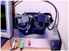
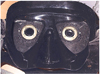
The hardware consisted of a head-mounted device to which a charge coupled device (CCD) camera was attached, and a control part to regulate electric power and stimulation (Fig. 1, 2). An infrared filter was attached to the headmounted device, and pupil images were obtained in the dark visual field. Thirty frames of images per second were sent to a computer. For the light excitement, 4 light emitting diodes (LED) and infrared LED were installed (Fig. 2). The control part consisted of isolated power for electric safety, and a microcontroller for the regulation of stimulatory LED. The stimulation parameters, including duration, frequency and brightness of LED to the single or both eyes, were controlled by a personal computer using serial communication.
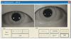
Upon stimulation, the images were taken by a CCD camera, transferred to the computer, compressed and stored. The location and size of the pupil on the stored images were calculated from image processing algorithm. To remove the infrared LED light reflected on the pupil, the closing operation was performed, a threshold was applied to the closing images, and the pixels below the threshold were obtained. By obtaining the outline of the image blocks that were obtained by the threshold, the pupil was isolated. The pupil was identified by ellipse fitting (Fig. 3). The distance between the pupil and the camera may vary with individual patients wearing a goggle and errors may be generated due to alterations in the size of the image projected on the image. Therefore, to reduce such errors, the distance between the two illuminating LEDs reflected on the pupil was measured to adjust for the errors generated due to the difference of the distance from the pupil and camera. As the distance between the pupil and the camera lengthens, the distance between the two illuminations reflected on the pupil shortens. Thus the distance of the reflected light was measured to adjust for the errors between individuals due to the distance of the pupil and the camera.
The following assessments were performed to evaluate the accuracy of the pupil measurement. In the first experiment, to assess the accuracy of the actual pupil measurement once the camera had been calibrated, the distance between the pupil and the camera was fixed at 25 mm, and the size of 9 pupil images, printed as 5 by 9 mm in size at 0.5 mm interval, was measured. Assuming that the camera was calibrated and proceeding with the 5 mm pupil images as the standard, all images showed a small range of error, within 0.2 mm. Other measurement errors, in addition to those due to the pupillography itself, may have included the errors generated during the manual measurement of the pupil size.
Second, the pupil size was fixed, and the effect of variation in distance from the camera to the pupil on the pupil measurement errors was assessed. The change of the image sizes formed on the camera was assessed while the distance between the camera and the pupil image was varied to 25±5 mm. There was a change of approximately 15 pixels when the distance from the eye to the camera was varied by ±5 mm, and the maximum error rate was 15% for the maximum change of 5 mm. The relationship between the error and the distance was linear.
Based on these results, we believed that the necessity for the patient to wear a goggle will alter the location of the camera according to individual head shape and eye position, and that adjustment is therefore required. To adjust for the error generated by the distance between the camera and eye, the change of the location of the light source reflected on the pupil was utilized. As both the size of the pupil imaged on the camera and the relative distance of the location of a pair of LED images reflected on the corneal surface are affected by the distance from the camera to the eye, the obtained pupil size could be standardized. For this assessment, the location of the camera was moved while the patient was wearing a goggle in the dark field, and the relationships between the camera adjustment, the change of the distance between the camera and the eye, and the change of the relative distance of the reflected light source were analyzed.
From the result, although the pupil size in the dark field did not change as the distance between the camera and eye changed, the pupil size on the camera and the relative distance of the reflected light source changed simultaneously. To adjust for this variation, the following compensation algorithm was applied:
(the pupil size at the standard distance)=(the size of pupil measured)-α* (relative distance of the reflected light source),
where α was an experimentally determined constant. The results confirmed that the maximum error of the pupil size was 39% without adjustment, and maximally 3.3% with adjustment. As the error was approximately 0.15 mm, it was considered safe to ignore.
Results
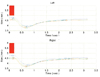
A pupillography test was developed that records the reaction of the pupil by CCD camera in response to the stimulation of a visible LED and an infrared LED, sends the images to a personal computer, and analyzes and presents the results graphically. The pupil images of both eyes, 320×240 in size and 30 images per second, were stored. On the stored images, imaging treatment and standardization allowed the change of the actual pupil size and the reaction speed to be measured (Fig. 4).
Discussion
Except for the pupillography test, most ophthalmologic tests are dependent on the subjective response of patients. For example, in the visual acuity test, the level when patients claim that they can no longer see becomes their vision. Similarly, in the visual evoked potential that many people believe to be objective, abnormal results may be obtained with an off-center stimulation, focusing on other objects, or voluntary defocusing, etc.5 However, pupillography is an important objective diagnostic tool for clinicians. In addition, the swinging flashlight test is very sensitive in the detection of a minor abnormality.2-4 Pupillography can be helpful for the diagnosis of tonic pupil, Argyll-Robertson pupil, Parinaud's syndrome, and third cranial nerve palsy, and for the differentiation of Horner syndrome and physiological anisocoria. Furthermore, as it can detect RAPD, it can help in the early diagnosis of diseases of the optic nerve, retina, and visual pathway. Particularly, in cases with abnormalities in the peripheral visual field while central vision is retained, diagnosis may be delayed as long as the patient's vision is good. However, as pupillary reactions concur to the change of visual field,6 this kind of abnormality could be detected. Even in cases showing weak RAPD such as amblyopia or glaucoma, the abnormality can be detected in their early period.7,8 In malingering patients who claim a lack of vision in one eye, if RAPD of the claimed eye were not detected, it could be used as a basis for convincing the patient otherwise. Pertinent to refractive surgery, it could help to determine the surgical range of refractive surgery by measuring the pupil size.1-4
In regard to pupillography, Lowenstein,9 and Lowenstein and Loewenfeld10 have introduced a modernized pupillography test. Subsequently, Thompson,11 Fison et al,12 and Cox13 confirmed RAPD by swinging flashlight test using a pupillography test. The presently available instruments are the P2000D Dynamic Pupillometer® (Procyon Instruments Ltd.), handheld Colvard pupillometer (Oasis Medical), SWIFT (Steinbeis Trasferzentru, Biomed Optik, Germany), Visual Pathway Binocular Pupillometer (Visual Pathways Inc. Prescott, AZ, USA), Micromeasurements System 9000 (Micromeasurements, Keith Sherman), etc.3 They analyze the pupil by taking images of the pupil using an infrared camera similar to our own instrument. The advantage of our instrument, however, is that it accounts for the goggle shape that blocks the light completely. Therefore, regardless of the light in the vicinity, pupil reactions can always be assessed even in the darkness. Presently, as pupillography is not available in Korea, a comparison with existing instruments was not feasible. For the clinical application of this newly developed Korean pupillography instrument, future clinical studies on a large number of patients are required.
 XML Download