

 PDF
PDF ePub
ePub Citation
 Print
Print


INTRODUCTION
In 1965, Parkinson, the first deviser of the triangular space around cavernous sinus (CS), described the triangle between the trochlear and ophthalmic nerves in order to safely approach the lesion at the internal carotid artery (1). Since Parkinson, the triangular spaces around the CS were devised by several studies by clinical anatomists and neurosurgeons (234567). Recently, as noninvasive surgery such as radiosurgery or endovascular surgery develop, direct surgery through the triangular spaces around CS is less employed. However, patients with special condition still require the direct surgery through the CS triangles (8).
Various studies have described the triangular space around CS (234567). However, the definitions of the triangles of the studies differed, although the definition must be consistent to be able to be used in diagnosis and operation. Moreover, the names of each triangle varied in each study, which impedes easy and convenient learning of the triangles.
Another problem was that educational materials for learning the triangles were insufficient. Most materials were hitherto photos, videos, CTs, and MRIs. However, in the photos and videos, the structures related to the triangles could not be well-observed and there was confusion of orientation because of inconsistent and subjective viewing angles of researchers. CTs and MRIs did not have sufficient resolution and coloration for observing the small nerves and vessels around the CS. Last, there was no proper schematic diagram for easy and accurate understanding of the triangles. Recently, because training opportunities of actual surgery as an observer or an assistant are narrowing due to noninvasive surgery, the need for new educational materials for clinical neuroanatomy including CS triangles is even greater.
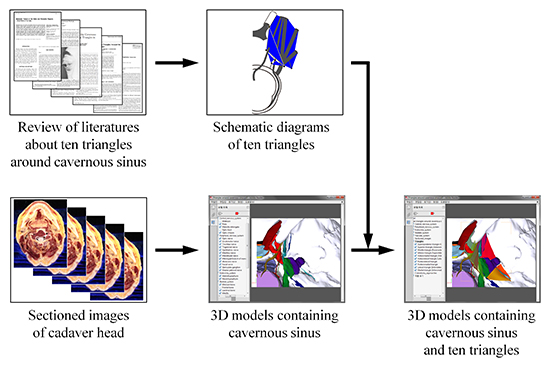
The purpose of this study is to provide two and three dimensional educational materials for accurate study of the triangles and nearby structures. To achieve these purposes, the triangles around the CS were rearranged and the educational materials for the triangles, consisting of schematic diagram and three dimensional (3D) models with sectioned images, were created.
MATERIALS AND METHODS
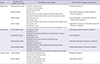
Papers about the triangles around the CS since 1965 were searched in PubMed of United States National Library of Medicine and National Institutes of Health (http://www.ncbi.nlm.nih.gov/pubmed/). Referring to numerous other studies, the boundaries and locations of the ten triangles were analyzed (Table 1). Sequentially, the newly defined triangles were drawn into a schematic diagram using Adobe Illustrator (Adobe Systems, Inc., San Jose, CA, USA) (Fig. 1A).
Table 1
Reorganized triangles in three groups around the cavernous sinus for approaching core of head
| Groups | The names of the triangles in this study | The definitions of the triangles | The names of the triangles in other studies |
|---|---|---|---|
| Medial group | Superoposterior triangle | (V) Anterior clinoid process | Oculomotor triangle (2) |
| (V) Posterior clinoid process | |||
| (V) Apex of petrous part | |||
| Superior triangle | (B) Optic nerve | Anteromedial triangle (2), Clinoidal triangle (6), Dolenc's triangle (22) | |
| (B) Oculomotor nerve before entering the superior orbital fissure | |||
| (B) Dural fold between dural entries of optic and oculomotor nerves | |||
| Middle triangle | (B) Oculomotor nerve | Paramedial triangle (2), Paramedian triangle (5), Supratrochlear triangle (6) | |
| (B) Trochlear nerve | |||
| (B) Dural fold between dural entries of oculomotor and trochlear nerves | |||
| Inferior triangle | (B) Trochlear nerve | Superolateral triangle (23), Infratrochlear triangle (6), Parkinson's triangle (2) | |
| (B) Ophthalmic nerve | |||
| (B) Dural fold between dural entries of trochlear and ophthalmic nerves | |||
| Lateral group | Anteromedial triangle | (B) Ophthalmic nerve | Anterolateral triangle (2), Mullan's triangle (3) |
| (B) Maxillary nerve | |||
| (B) Between the superior orbital fissure and the foramen rotundum | |||
| Anterolateral triangle | (B) Maxillary nerve | Lateral triangle (2) | |
| (B) Mandibular nerve | |||
| (B) Between the foramen rotundum and foramen ovale | |||
| Posterolateral triangle | (B) Mandibular nerve | Posterolateral triangle (2), Glasscock's triangle (2) | |
| (B) Greater petrosal nerve | |||
| (B) Between foramen ovale and hiatus of greater petrosal nerve | |||
| Posteromedial triangle | (B) Trigeminal ganglion | Posteromedial triangle (2), Kawase's triangle (2) | |
| (B) Greater petrosal nerve | |||
| (B) Between hiatus of greater petrosal nerve and apex of petrous part | |||
| Posterior group | Lateral triangle | (V) Dural entry of trochlear nerve | Inferolateral triangle (2) |
| (V) Dural entry of abducens nerve | |||
| (V) Apex of petrous part | |||
| Medial triangle | (V) Dural entry of trochlear nerve | Inferomedial triangle (2) | |
| (V) Dural entry of abducens nerve | |||
| (V) Posterior clinoid process |
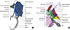
Fig. 1
Schematic diagram and three dimensional (3D) models of reorganized triangles around the cavernous sinus (superior view of right side). In a schematic diagram, ten triangles are easily comprehended (A) and, in the 3D models, each structure related to the triangles is shown accurately (B). 1 = superoposterior triangle; 2 = superior triangle; 3 = middle triangle; 4 = inferior triangle; 5 = anteromedial triangle; 6 = anterolateral triangle; 7 = posterolateral triangle; 8 = posteromedial triangle; 9 = lateral triangle; 10 = medial triangle; II = optic nerve; III = oculomotor nerve; IV = abducens nerve; V1 = ophthalmic nerve; V2 = maxillary nerve; V3 = mandibular nerve; VI = abducens nerve; TG = trigeminal ganglion.
In our previous experiment, we made high quality and true color sectioned images of head (horizontal, coronal, and sagittal planes; intervals, 0.1 mm; pixel size, 0.1 mm × 0.1 mm; color depth, 48 bits color) (9). We also made segmented images of structures related to oculomotor, trochlear, and abducens nerves (10). Among the segmented structures, 36 structures related to the CS were selected for this study (Table 2).
Table 2
Forty-four structures, including the cavernous sinus and neighboring structures, segmented in sectioned images and reconstructed to build three dimensional models

| Systems (the numbers of the structures) | Structures |
|---|---|
| Skeletal system (17) | Parietal bone, Frontal bone, Occipital bone, Sphenoid bone, Posterior clinoid process, Anterior clinoid process, Middle clinoid process, Temporal bone, Ethmoid bone, Lacrimal bone, Nasal bone, Maxilla, Zygomatic bone, Mandible, Foramen spinosum,* Foramen ovale,* Apex of the petrous part* |
| Endocrine system (2) | Adenohypophysis, Neurohypophysis |
| Vascular system (8) | Internal carotid artery, Basilar sinus, Basilar plexus, Inferior petrosal sinus, Superior petrosal sinus, Cavernous sinus, Anterior intercavernous sinus, Posterior intercavernous sinus |
| Central nervous system (5) | Medulla oblongata, Pons, Midbrain, Optic chiasm, Optic tract |
| Peripheral nervous system (12) | Optic nerve, Oculomotor nerve, Trochlear nerve, Trigeminal nerve, Ophthalmic nerve, Maxillary nerve, Abducens nerve, Mandibular nerve,* Meningeal branch of mandibular nerve,* Facial nerve,* Greater petrosal nerve,* Geniculate ganglion* |
Additionally, eight structures were newly outlined on the horizontal sectioned images using Adobe Photoshop (Adobe Systems, Inc.) (1112). The outlined structures were filled with different colors using Photoshop (Table 2).
In Mimics version 10.01 (Materialise, Leuven, Belgium), the outlines of each structure in the segmented images were built automatically by surface modeling to make 3D models. The 3D models of each structure were exported as stereolithography (STL) files. After the STL files were imported on Maya version 2015 (Autodesk, Inc., San Rafael, CA, USA), the flaws of the models were found and amended using ‘Sculpt geometry tool' (1314).
According to reorganized triangles (Table 1) and schematic diagram (Fig. 1), the triangular surfaces were drawn between 3D models of each structure, using ‘Create polygon tool' of Maya.
When the 3D models were observed, the subject's cavernous sinus and surrounding structures had normal anatomy. The cavernous sinus was almost symmetric without any morphological abnormalities. The cranial nerves including the optic, oculomotor, trochlear, trigeminal, ophthalmic, maxillary, mandibular, abducens, and facial nerves had normal shape and were at proper locations. Even the small branches of them like the meningeal branch of mandibular nerve and the greater petrosal nerve were intact.
Twenty three coronal sectioned images at 2 mm intervals were embedded in conforming position of the 3D models on Maya as follows. Using 'Polygon Plane: Create a polygonal plane on the grid', two blank surfaces the size of the sectioned image were created. In the 3D models of the structures, the first and last surfaces were placed at two exact positions with 44 mm intervals. The first surface was copied and pasted 21 times. With the 'snap align objects', 23 surfaces (the first one, the last one, and the copied ones) were aligned at 2 mm constant intervals. Through 'Material Attributes...' of a surface, 'File Attributes' of 'Lambert' was opened and 23 coronal sectioned images were embedded. 3D models of the structure with triangular surfaces and the sectioned image were exported as Virtual Reality Modeling Language 2.0 (VRML2) files. In setting the alignment of the sectioned images, the anterior and posterior commissures were regarded as the reference points (15). Therefore, the position of the coronal images on 3D models was described referring to the midpoint of the anterior and posterior commissures (Fig. 2).
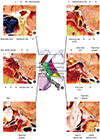
Fig. 2
Three dimensional models (A) embedding the coronal sectioned images of each triangle. At coronal +30 mm, the superior triangle (2) is located between the optic (II) and oculomotor (III) nerves (B). At coronal +14 mm, the superoposterior (1), superior, middle (3), and inferior (4) triangles can be identified with the optic, oculomotor, trochlear (IV), and ophthalmic (V1) nerves (C). At coronal +10 mm, the anteromedial (5) and anterolateral (6) triangles are found between the ophthalmic, maxillary (V2), and mandibular (V3) nerves, while posterior (Post.) clinoid process which is the vertex of the superoposterior triangle is visible (D). At coronal +4 mm, the medial triangle (10) is located between the dural entries of trochlear and abducens (VI) nerves, while the inferior and medial triangles are observed around the dural entry of trochlear nerve (E). At coronal 0 mm, the posterolateral (7) and lateral (9) triangles are partly observed (F). At coronal -6 mm, the posteromedial triangle (8) is identified between the apex of petrous part of temporal bone and the greater petrosal nerve (G). When setting the positions of the images, the anterior and posterior commissures were regarded as the reference points (25). The 1 = superoposterior triangle; 2 = superior triangle; 3 = middle triangle; 4 = inferior triangle; 5 = anteromedial triangle; 6 = anterolateral triangle; 7 = posterolateral triangle; 8 = posteromedial triangle; 9 = lateral triangle; 10 = medial triangle; II = optic nerve; III = oculomotor nerve; IV = abducens nerve; V1 = ophthalmic nerve; V2 = maxillary nerve; V3 = mandibular nerve; TG = trigeminal ganglion.
After each 3D model in VRML2 files was imported on Deep Exploration version 6.3 (Right hemisphere, Ltd., Pleasanton, CA, USA), the 3D models were categorized into 5 systems (Table 2). The categorized 3D models with triangles and sectioned images were exported as a VRML2 file. On Adobe 3D Reviewer (accompanying software of Acrobat 9.0 Pro Extended of Adobe Systems, Inc.), 3D models in VRML2 file were colored and named properly. The 3D models were saved as a portable document format (PDF) file (Figs. 1B, 2, and 3A).
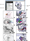
Fig. 3
In the PDF file, windows showing each 3D model and bookmarks of clinical trials. Images from left column are derived from references: B (22), D (18), F (20), and H (21). In the model tree, bookmark, and surface models windows of the PDF file, user can select 3D models of each structure, sectioned images, and clinical trial (A). Regarding clinical approaches, textbook figures (B, D, F, H) and correspondence with 3D models of this study (C, E, G, I) are shown. Interhemispheric approach through the superoposterior and superior triangles (B, C), pterional approach through the middle, inferior, anteromedial, and anterolateral triangles (D, E), middle cranial fossa approach through the posterolateral and posteromedial triangles (F, G), and retromastoid suboccipital approach through the lateral and medial triangles (E) can be operated virtually.
In the PDF file, clinical approaches were marked at the ‘Bookmark window'. First we selected the triangles and related surgical approaches. The selected approaches were interhemispheric approach (1617), Pterional approach (1819), middle cranial fossa approach (20), and retromastoid suboccipital approach (21). For showing these surgical approaches, 3D models of each triangle and related structures were displayed at the ‘Surface model window' and the combination was marked at the ‘Bookmark window' (Fig. 3).
RESULTS
By analyzing other studies, the triangular spaces around the CS were reorganized into ten triangles in three groups. All triangles were located around the sella turcica which are placed at the median plane; therefore, we categorized the triangles into medial, lateral, and posterior groups. Names of triangles were decided according to location (Table 1). Based on the analysis of triangles, the schematic diagram of the reorganized triangles was drawn. In the diagram, vertices and borders of triangles were indicated by each structure and only the superior view was employed in order not to confuse the orientation (Fig. 1).
In describing the parts of the internal carotid artery, Terminologia Anatomica was observed: cervical part, petrous part, cavernous part, cerebral part, and carotid siphon (2425). In the PDF file (file size, 228 MBytes), 3D models of 44 structures were presented and the ten triangular spaces were indicated (Figs. 1 and 3, Table 2). The models could be rotated or magnified freely to simulate a patient's surgical position (13). Furthermore, in the PDF file, 23 coronal sectioned images at 2 mm intervals corresponding to location of 3D structures could be shown (Fig. 2).
By comparing the schematic diagram of ten triangles with the 3D models and the sectioned images, the schematic diagram was proven to be accurate (Figs. 1 and 2). The analysis results of ten triangles were described through the schematic diagram and the 3D models with the sectioned images as follows. The borders and vertices of ten triangles are explained in Table 1.
Interhemispheric approach can be virtually performed in the PDF file as follows (23). After virtually drilling the central portion of the frontal bone, virtual equipment can be accessed at superoposterior and superior triangles of the medial group. Through the triangles, well selected carotid-opththalmic aneurysm can be approached. Moreover, the superior and inferior of the carotid siphon can be observed (Figs. 3B and 4).
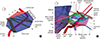
Fig. 4
The relationship of each triangle and each part of the internal carotid artery at lateral view of the right side for clinical approaches. On schematic drawing, each part of the internal carotid artery can be identified through the triangles except lateral and medial triangles of the posterior group (A). On the three dimensional models, interhemispheric approach, pterional approach, middle cranial fossa approach, and retromastoid suboccipital approach are demonstrated to access the internal carotid artery (B). 1 = superoposterior triangle; 2 = superior triangle; 3 = middle triangle; 4 = inferior triangle; 5 = anteromedial triangle; 6 = anterolateral triangle; 7 = posterolateral triangle; 8 = posteromedial triangle; 9 = lateral triangle; 10 = medial triangle; II = optic nerve; III = oculomotor nerve; IV = abducens nerve; V1 = ophthalmic nerve; V2 = maxillary nerve; V3 = mandibular nerve; VI = abducens nerve; VII = facial nerve; TG = trigeminal ganglion.
Pterional approach can be virtually performed as follows (181926). After virtually opening the pterion part of the cranium, a neurosurgeon can observe the carotid-cavernous fistula below the temporal lobe through the middle and inferior triangles of the medial group or the anteromedial and anterolateral triangles of the lateral group (Figs. 3D, 3E, 4 and Table 1). Additionally, the cavernous-pterygoid venous anastomosis can be accessed by the anterolateral triangle (23). When intracranial inflammation causes the palsy of abducens nerve, the nerve's most portions can be approached through the inferior triangle of medial group and its distal portion through the anterolateral triangle of lateral group (Figs. 3B, 3C, and 4A).
In case of the aneurysm of the petrous part of the internal carotid artery or the petroclival meningioma, bypass grafting can be done by through the middle cranial fossa approach (20). After retracting the temporalis, opening the pterion, and lifting the temporal lobe, the virtual equipment can reach the posterolateral and posteromedial triangles. Through the triangles, the aneurysm of the petrous part or the petroclival meningioma can be treated (Figs. 3F, 3G, and 4) (27). These days, the rhomboid space expanded from the posteromedial triangle is employed for greater surgical freedom (28). When treating carotid siphon bleeding, temporary occlusion of the internal carotid artery can be performed through the posterolateral triangle (Figs. 3F, 3G, and 4).
Rarely, retromastoid suboccipital approach is employed in accessing the small branches of the cavernous part of the internal carotid artery (21). After making a hole at the occipitomastoid suture, virtual equipment is inserted at the lateral and medial triangles of posterior group through the gap between the cerebellum and the petrosal part of the temporal bone. Through the triangles, the equipment arrives at the small branches of the artery (Figs. 3H, 3I and 4). However, surgeons must be cautious about the basilar venous plexus near the triangles.
DISCUSSION
By analyzing other studies, the ten triangles were rearranged and new nomenclature of the triangles was suggested according to the positions or directions of the triangles. The accuracy of the rearranged triangles was proven by the 3D models and embedded sectioned images. In addition, we provided freely the educational materials of this study, which consisted of the schematic diagram (Figs. 1A and 4A) and the realistic 3D models including coronal sectioned images (Figs. 1B, 2, 3, and 4B).
In this study, inappropriate vertices of triangles from other studies were revised. For example, a vertex of posterolateral and posteromedial triangles was defined with respect to the geniculate ganglion which is inappropriate (6). First, the geniculate ganglion cannot be observed before breaking to open the petrous part of temporal bone. Second, observation of intraosseous structures by breaking the cranium in the intracranial cavity is very difficult and dangerous. Therefore, in this study, vertices of the triangles were defined using only visible structures in the intracranial cavity. A vertex of the posterolateral and posteromedial triangles was defined with the hiatus of the greater petrosal nerve, rather than the geniculate ganglion (Figs. 1 and 2, Table 1).
Borders in each triangle could be decided accurately based on precise vertices of this study. A researcher defined three borders of posterolateral triangle; mandibular nerve, greater petrosal nerve, and between foramen spinosum and arcuate eminence of the petrous part of temporal bone (23). However three borders would not form a triangle because two borders (two nerves) and the other border (between the foramen and the eminence) were not joined. Therefore, in this study, we rearranged three borders that could form a triangle. For example, in case of the borders of the researcher (23), we defined two borders (mandibular nerve and greater petrosal nerve) and another border (between the foramen ovale and hiatus of the greater petrosal nerve). Since mandibular nerve and greater petrosal nerve enter bone through foramen ovale and the hiatus, they were joined to form a perfect triangle (Figs. 1 and 2, Table 1).
Triangles could be decided accurately. In this study, accurate vertices and borders were determined and their accuracy was proved by our sectioned images and 3D models; consequently, triangles in this study were also accurate (Figs. 1 and 2, Table 1). In understanding the triangles around the CS, conventional cadaver dissection is the best way. However, the easily obtainable PDF file with the 3D models can be an auxiliary material for the preview or review of dissection.
Traditionally in anatomy, a simplified diagram is employed to assist rudimentary understanding of structures' shape, location, or position, particularly to novice medical students. After understanding the structures, 3D models are used in order to present anatomy with regard not only to the location and position of the structures but also to their relationship. However, neither a simplified diagram nor 3D models were provided, although the triangles were very complicated. Therefore, in this study, the schematic diagram of the triangles around the CS was drawn (Figs. 1A and 4A) so as to elucidate the triangles easily. The PDF file including the 3D models was made (Figs. 1B, 3, and 4B) in order to grasp the triangles stereoscopically. Consequently, we suggest others to use the schematic diagram for their anatomy theory lecture and to utilize the 3D models with the sectioned images for cadaver dissection.
We also included two supplementary materials, the surgical approaches bookmarks and the coronal sectioned images in the PDF file. The surgical approaches bookmarks would be useful in explaining the orientation of the surgery (Fig. 3). The coronal sectioned images are very helpful to understanding the sectional anatomy of the CS region. Furthermore, if the a doctor used the 3D models with these features in this study, he or she could explain well and easily the findings on a patient's MRI or CT to the patient (Fig. 2).
The educational materials provided in this study can complement each other, producing a synergic effect. The schematic diagram can be used for easily understanding morphology of structures but cannot be used for learning detailed anatomical knowledge of the structures because it is very simple. Contrariwise, using the 3D models, the detailed anatomical knowledge of structures can be memorized easily, however understanding the knowledge is not easy because it is very complicated. Given their complementary relationship, we suggest that both the schematic diagram and the 3D models be employed when teaching.
Nowadays, emerging radiosurgery and endovascular surgery are becoming the mainstream in brain surgery for its superior safety level and short recovery time. However, some brain diseases such as some tumors like meningioma, pituitary adenoma, schwannoma, and chondroid tumor still need to be invasively operated by a neurosurgeon (2930313233). The debate between endovascular coiling and extravascular clipping of aneurysm still requires more study (3435). When endovascular embolization or balloon occlusion of carotid-cavernous fistula is failed, conventional surgery is considered (36). Therefore, neurosurgeons with competent surgical skill are still needed.
In order to acquire competent surgical skill, a doctor has to observe and attend the actual operation as an assistant. However, surgical training opportunity for doctors is narrowing because the noninvasive surgery is mainstream. To compensate, a doctor certainly needs the educational materials for surgical training. Therefore, in this study, we provided the educational materials, consisting of a schematic diagram for understanding the region, sectioned images for interpreting CTs and MRIs, and 3D models for absorbing stereoscopic knowledge.
By using our schematic diagram of this study, ten triangles around the CS can be understood easily. By using the 3D models with sectioned images, ten triangles and related structures could be studied accurately. We expect that our data will contribute to anatomy education, surgery training, and radiologic understanding. In addition, we are certain that the combination of our data and existing learning tools, such as surgery videos and cadaver dissection, will be highly effective. We are also sure that virtual approaching of ten triangles of this study is becoming increasingly necessary as real surgical training opportunity is decreasing due to radiosurgery. All of the materials can be downloaded for free at our homepage.
 XML Download