

 PDF
PDF ePub
ePub Citation
 Print
Print


INTRODUCTION
Thoracic endovascular aortic repair (TEVAR) is an effective therapy for various thoracic aortic pathologies, including aortic aneurysm, aortic dissection, and traumatic aortic transection, particularly in patients with a high operative risk (1, 2, 3, 4, 5). TEVAR has a short procedure time, a low complication rate, and a low hospital mortality compared to open surgery for repair of the thoracic aorta (5, 6, 7, 8, 9). However, it is difficult to perform TEVAR in patients with a short proximal stent graft landing zone (10, 11). Most companies that fabricate thoracic aortic stent grafts recommend their use in patients with a proximal landing zone of > 15 mm. When patients have a short proximal landing zone near the aortic arch, there is an high risk of endoleak, migration of the stent graft due to angulation of the aortic arch, and high blood pressure in the aorta (6, 9, 12). Thirty to fifty percent of cases with aortic aneurysm, aortic dissection, and traumatic aortic transection involve the aortic arch (13 ,14, 15, 16). Several branched aortic stent grafts and fenestrated aortic stent grafts for aortic arch disease have been reported, but these products have also not been made commercially available because of various problems (17, 18, 19, 20). Here, we developed a convenient fenestrated aortic arch stent graft (FASG) with a preloaded catheter for the supraaortic arch vessels, and performed a preclinical study to evaluate this FASG in swine.
MATERIALS AND METHODS
Design and manufacture of the stent graft
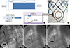
The FASG is composed of a main stent graft with preloading catheters and stent grafts for the supraaortic arch vessels. The FASG developed here has a preloaded catheter (1.14 mm in diameter) inside the main delivery system to select the carotid artery, the innominate artery, and the subclavian artery. The preloaded catheter links to a distal side hole (8 mm in diameter), and the distal port of the preloaded catheter protrudes from the distal portion of the deployment section of the main delivery system. A 0.035-inch guidewire can reach the carotid and subclavian artery through this preloaded catheter (Fig. 1). This side hole is indicated with a circular gold marking, while either side of it is indicated with a straight gold line to identify the side hole easily. The framework of the FASG is composed of 0.234-mm nitinol, while the graft is made from polytetrafluoroethylene (PTFE). The diameter and length of the FASG are 34 mm and 110 mm, respectively. The bare area of the FASG (i.e., the area lacking PTFE around the nitinol frame) is 30 mm in length from the proximal end of the graft and is oversized at 38 mm in diameter for preventing migration of the FASG. The proximal end of the FASG is tied up at 2 points to be movable both when the FASG is partially deployed and when it is deployed completely at the end of stent graft deployment (Fig. 2, 3). The profile of the FASG is 18 French, including the preloaded catheter. The stent graft for the supraaortic arch vessels is 10 mm in diameter and 40 mm in length. The stent graft for the supraaortic arch vessels was designed to have flare-shaped bare areas each 5-mm in length at both the proximal and distal ends of the stent graft.
Study protocol
Six FASGs with 1 preloaded catheter and 1 fenestration (one FASG) and 5 FASGs with 2 preloaded catheters and 2 fenestrations (two FASG) were placed through the iliac artery in 11 swines (70-80 kg). The presence of endoleaks and the patency and deformity of the grafts were evaluated with computed tomography (CT) at 4 weeks after the procedure. Postmortem examination was performed at 8 weeks to evaluate the gross morphology, patency, and deformity of the FASGs and branch stent grafts. This preclinical study protocol was approved by the animal experimental committee of Pusan National University Hospital.
Procedure technique
The pigs were sedated with an intramuscular injection of ketamine hydrochloride (10 mg/kg) and xylazine (2 mg/kg). Sedation was maintained with inhalated isofluorane. The iliac artery was then exposed by a retroperitoneal approach, and 10,000 units of heparin were administered intravenously. The diameter of the iliac artery was measured following angiography. We inserted an 18 French sheath into the iliac artery and placed a 0.035-inch extra-stiff guidewire (Lunderquist™, COOK, Bloomington, IN, USA) in the ascending aorta. A marked pigtail catheter was inserted through the other iliac artery into the aorta to examine both the aorta and the carotid arteries during the procedure. The marked side hole was identified in advance under fluoroscopy (Fig. 2). The one FASG advanced into the aortic arch, with the fenestration side hole kept facing the carotid artery. We partially deployed the FASG up to the fenestration side hole and selected left carotid artery using the 0.035-inch hydrophilic guidewire (Terumo, Tokyo, Japan). We moved the FASG forward to fit the fenestrated side hole into the left carotid artery and deployed the FASG completely. The delivery sheath of the FASG was removed from the aorta, but the guidewire for the left carotid artery was maintained. We then advanced the stent graft (10×40 mm) for the left carotid artery. Next, percutaneous transluminal balloons (8×40 mm) were inflated to create good connections between the main FASG and the stent graft for the left carotid artery. In case of the two FASG, we partially deployed the FASG up to the fenestration side holes and selected right and left carotid artery using the 0.035-inch hydrophilic guidewires (Terumo). We moved the FASG forward to fit the fenestrated side holes into the right and left carotid artery and deployed the FASG completely. The delivery sheath of the FASG was removed from the aorta, but the guidewires for the right and left carotid artery was maintained. We then advanced the stent grafts (10×40 mm) for the right and left carotid artery one after another. Next, percutaneous transluminal balloons (8×40 mm) were inflated to create good connections between the main FASG and the stent grafts for the carotid arteries. Aortography was performed to check the flow of the carotid arteries for detecting endoleaks (Fig. 3, 4).
RESULTS
Eleven pigs were successfully implanted with FASGs. The mean procedure time for the one and two FASG groups was 30.2 (27.9-34.5) min and 43.1 (39.2-53.7) min, respectively. Additionally, the mean time for the selection of the carotid artery was 4.8 (4.2-5.5) min and 6.2 (4.6-9.4) min, respectively (Table 1). Major adverse events such as death, cerebral ischemia, limb ischemia, organ infarction, paraplegia, serious infection, and vascular complications were not observed in the 11 pigs. Ten of the pigs survived the 8-week observational period. However, 1 pig with a one FASG died at 4 weeks after the CT examination; the death was likely related to the high dose of ketamine used for the CT examination. Vascular damage to the iliac artery, aorta, and carotid artery was not detected in any of the 11 pigs during the procedure (Table 1). Moreover, none of the pigs showed migration of the FASG. We were able to select the carotid arteries easily in all 11 pigs using the preloaded catheter and had no instances of selection failure for these carotid arteries. The FASG moved easily after the partial deployment for fitting the fenestrated side holes into the carotid arteries.
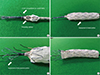
For both the one and two FASG groups (n=6 and n=5, respectively), no endoleaks, no retrograde type A aortic dissection, no disconnection of the stent grafts, and no occlusion of the stent grafts for the carotid arteries were observed in the CT findings at 4 weeks (Fig. 5). Autopsy was performed on 1 pig at 4 weeks. The remaining 10 pigs were sacrificed at 8 weeks for autopsy. No disconnection or tearing of the stent grafts, no fractures in the stent grafts, no retrograde type A aortic dissection, and no occlusion of the stent grafts for the carotid arteries were found in the postmortem gross findings (Fig. 6).
DISCUSSION
A short landing zone for an aortic arch pathology can be problematic in performing TEVAR. In response to this particular issue, a few doctors have developed fenestrated or branched stent grafts for aortic arch disease. Inoue et al. (17) developed a branched aortic stent graft for aortic arch disease and attempted to use it in the treatment of 15 patients with thoracic aortic aneurysms and aortic dissections. Single-branched and triple-branched stent grafts were used in 14 patients and 1 patient, respectively. In 2 patients, the single-branched stent graft did not pass through the 22F sheath used. In 1 patient, the right external iliac artery ruptured during the procedure. However, complete thrombosis of the aneurysm was achieved in 11 patients (73%). In terms of complications, 4 persistent leaks and 1 minor leak occurred. Cerebral infarction occurred in 1 patient, and abdominal aortic aneurysm rupture was reported for 1 patient. The branched stent graft of Inoue has not become commercially available because the stent graft has the large profile of 22-24 French, a long procedure time, a complicated procedure method, and the requirement for surgical exposure of the carotid and subclavian arteries (17). The free end of traction wire attached to tip of the branched stent graft was caught and pulled back by a gooseneck snare wire through the left subclavian artery, carotid, and innominate arteries to deploy the folded branch stent graft. This complicated procedure method resulted in a long procedure time. Our FASG has a small size, a short procedure time, and a simple procedure method. Moreover, the FASG has a size of 18 French, which is comparable to the 7-mm diameter of the iliac artery. Of note, no iliac artery perforations were observed in our study. The mean procedure time was dramatically shortened because our FASG had a preloaded catheter with a diameter of 1.14 mm inside the main delivery system to select the carotid, innominate, and subclavian arteries. This system reduced the procedural time and made the procedure method easy. However, the selection of the carotid and subclavian arteries in the diseased aorta of humans will be difficult because of angulation of the diseased aortic arch and the variable location of the carotid and subclavian arteries. Hence, we prepared 0.035 inch, 0.018 inch shapeable guidewires to enable easier selection of the carotid and subclavian arteries. Sometimes, a gooseneck snare inserted through the left brachial artery can be used to catch the preloading wire in patients with an angulated aortic arch. As such, we do not recommend the FASG in patients with a severely angulated aortic arch.
Wei et al. (20) developed a 3-part modular branched aortic stent graft and implanted it in canine models. However, this stent graft has not undergone a clinical study because of the long procedure time (320 min), complicated procedure method, and the need to surgically expose the carotid and subclavian arteries. Meanwhile, Yokoi et al. (21) developed a precurved fenestrated stent graft for aortic arch aneurysm and aortic dissection. This device made the fenestration site for the carotid artery subclavian artery in advance using 3D computed tomography. Yokoi et al. reported that 383 patients who required a stent graft in the aortic arch were treated with this precurved fenestrated stent graft. Technical and initial successes were achieved in 380 and 364 cases, respectively. The mean operative time was 161±76 min, and the mortality rate was 1.6% (21). However, this type of fenestrated stent graft has the risks of inaccurate deployment and stent graft migration, and the fenestrated site may be difficult to fit into the carotid artery accurately. Our FASG has a preloaded catheter, and the 0.035-inch guidewire can be placed into the carotid and subclavian arteries in advance. This wire can prevent migration of the FASG during deployment and can fit the branch of stent grafts to the carotid and subclavian arteries accurately. Further, the delivery sheath of the FASG was removed from the aorta, with the guidewires for the carotid arteries maintained in place, and the advanced branch of stent grafts were fit to the carotid and subclavian arteries respectively. We considered that a weak portion of the FASG might be connections of the main stent graft and the branch of stent grafts. The small gap between the 2 stent grafts could make an endoleak. Hence, the FASG was made with a side hole, 8 mm in diameter, and with a branch of stent graft oversized at 10 mm in diameter. Additionally, percutaneous transluminal balloons were inflated to create good connections between the main FASG and the stent grafts for the carotid arteries. No endoleaks were observed in the animal study. In the postmortem gross findings, the main body of the FASG and stent grafts for the carotid arteries adhered to the aorta and carotid arteries tightly.
Based on our findings, we have submitted an application for a Phase I clinical study to the Korea Food and Drug Administration, and we will perform a clinical study in the near future.
Our animal study has a few study limitations. In our animal study, we were unable to develop an aortic arch aneurysm model. To our knowledge, the development of this type of model is not possible. Hence, it was difficult to estimate precisely the occurrence of endoleaks for the connecting portion between the main stent graft and the branch of stent grafts. However, we did not detect any significant endoleaks.
Humans are anatomically different from pigs in several respects relevant to this study. Although pigs possess 2 carotid arteries that are uniform in size and located at regular intervals, the innominate, carotid, and left subclavian arteries are anatomically variable in humans. Therefore, we will be fabricating the FASG following a CT analysis of each patient. Moreover, the angulation of the aortic arch in pigs is different from that in humans. Hence, we prepared 0.035 inch, 0.018 inch shapeable guidewires to enable easier selection of the carotid and subclavian arteries. As such, we do not recommend the FASG in patients with a severely angulated aortic arch.
The FASG with the preloaded catheter for the carotid and subclavian arteries was developed for patients in whom the aortic pathology involves the aortic arch and only a short proximal landing zone is thereby available for the stent graft. In this study, we performed a preclinical study with this device in swine. The procedure with the FASG could be performed safely, had a short procedure time, and involved an easily performed technique. No endoleaks, no aortic dissections, and no disconnection, occlusion, or tearing of the stent grafts were found in the CT and postmortem gross findings. In conclusion, The FASG with the preloaded catheter developed here is comparatively safe and convenient in this preclinical study in swine.


 XML Download