

 PDF
PDF ePub
ePub Citation
 Print
Print


INTRODUCTION
Surface models, which are the empty three-dimensional images consisting of just surfaces, have much smaller file size than volume models. Therefore, surface models have advantage to be selected for display, rotated, and modified in a real time. For the realistic computer simulation of the liver in clinics, it is desirable to use detailed surface models of the hepatic duct, hepatic artery, portal vein, and hepatic vein inside the liver as well as surface models of the neighboring structures, i.e., stomach, duodenum, and so on (1). The surface models can be stereoscopically drawn with artistic skill and anatomical knowledge. On the other hand, objective surface models can be made from the scientific data as follows: structures are outlined in the serial images and after stacking the outlines, gaps between the outlines are filled with polygons, which is the surface reconstruction (2, 3).
Unfortunately, however, all the detailed structures inside and outside the liver cannot be simultaneously identified in the computed tomographs (CTs) or magnetic resonance images (MRIs) of abdomen, even though contrast medium is injected (4). For example, contrast medium never stays in all portal triad and hepatic vein at the same time. Moreover, in the clinical images of living persons, the structures tend to be obscure because of muscle and lung movements during scanning. Therefore, the serially sectioned images of cadaver such as the Visible Human Project data have to be used for identifying detailed structures. For the identification, the serially sectioned images have definite advantages of high resolution and real anatomical color. A minor problem with the Visible Human Project is that its data have missing images at a level of the liver as cadavers were separated by a saw (sawing thickness, 3 mm) prior to serial sectioning (5). Therefore, we considered to utilize the Visible Korean Human (VKH) data without missing images. The VKH data have another merit to include the serially sectioned images of good quality with 0.2 mm pixel size, which is smaller than 0.33 mm pixel size of the Visible Human Project. With the smaller pixel size, the more detailed structures are able to be outlined precisely (6, 7).
We recently produced surface models of the lower limb from VKH after we identified and outlined the lower limb structures, mostly muscles in serially sectioned images (8). Unlike specific software for surface reconstruction (e.g. SURFdriver™ version 3.56) (9), popular software (e.g. Alias™ Maya version 7.0) has an advantage that surface models can be built and elaborated without functional restriction and saved as a number of file formats. The popular software also has another advantage of being both widely available and relatively user-friendly. The established technique of surface reconstruction has time consuming problem to apply to lots of structures (8). So we attempted improving the technique to enhance automation extent on the popular software. Incidentally, it is hard to identify boundaries of eight hepatic segments in the serially sectioned images. Therefore, in the present study, we determined to divide one surface model of the liver referring to distribution of the portal vein.
Purpose of this research is to present the detailed surface models of the liver and neighboring structures, which can be applied to medical training systems of abdomen. The surface models, which will be distributed with the serially sectioned images, are expected to promote various kinds of computer simulation such as virtual hepatic segmentectomy and virtual laparoscopic cholecystectomy contributing to clinical practice. Another purpose is to introduce the advanced technique of surface reconstruction, which can be applied to making other useful surface models from serial images.
MATERIALS AND METHODS
In this study, we produced segmented images of 47 liver and neighboring structures from the VKH data; we built 47 surface models from the segmented images by using an advanced surface reconstruction technique on the popular software; we separated a surface model of the liver into those of hepatic segments according to branches of the portal vein.
A male cadaver was serially sectioned at 0.2 mm intervals. The sectioned surfaces were photographed by a digital camera (resolution, 3,040×2,008; Kodak™ DCS560) to create serially sectioned images (tag image file format [TIFF]; pixel size, 0.2 mm) (6). From the 8,510 serially sectioned images, we selected 277 serially sectioned images (2,515.tif, 2,520.tif ... 3,895.tif; intervals, 1 mm) of abdomen including the liver and related structures.
For the procedures of outlining, stacking, surface and volume reconstruction described below, several commercial software (abbreviation) was utilized: Adobe™ Photoshop version CS3 (Photoshop), Alias™ Maya version 7.0 (Maya), Autodesk™ AutoCAD version 2007 (AutoCAD), Autodesk™ 3ds max version 9.0 (3ds max), Rhinoceros™ Rhino version 4.0 (Rhino), 3D-Doctor™ version 3.5 (3D-Doctor).
Outlining and stacking
Forty-seven liver and surrounding structures, which would be outlined in the serially sectioned images, were chosen. The structures inside the liver included portal triad consisting of the hepatic duct, hepatic artery, and portal vein as well as the hepatic vein. Other structures outside the liver were the portal triad, stomach, duodenum, muscles, bones, skin, etc. (Table 1). In case of pipe-like structures such as ducts, arteries, and veins, luminal outlines were drawn because they were more distinct than mural outlines in the serially sectioned images. However, in case of the stomach and duodenum, mural outlines were drawn.
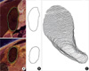
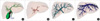
On Photoshop, the chosen structures were outlined in serially sectioned images. Structures, which were quite different in color from surroundings (e.g. blood vessels outside the liver, bones, and skin), could be outlined almost automatically using 'magic wand' tool; but less distinct structures (e.g. the liver, stomach, and muscles) were outlined semiautomatically using 'magnetic lasso' tool or 'quick selection' tool; and the graphically obscure structures (e.g. portal triad inside liver) were outlined manually only using 'lasso' tool. After outlining, segmented images were saved as Photoshop document (PSD) file (Fig. 1A, Table 2) (10).
On Photoshop, only outline of a structure in a segmented image was converted from bitmap to vector. The vectorized outline was saved as Adobe Illustrator (AI) file to acquire a vectorized segmented image (Fig. 1B). In the same manner, all the serial vectorized segmented images of a structure were produced from the other segmented images (Table 2) (8).
On Maya, all outlines of a structure were stacked. For example, two outlines of the gallbladder from two vectorized segmented images (2,925.ai and 2,930.ai) were moved downward from vertex at 2,925×0.2 mm and 2,930×0.2 mm distance, respectively in order to keep the gallbladder's horizontal-vertical proportion and its proper location. This was repeated automatically by the 'Maya script' tool until all 101 serial outlines of the gallbladder were appropriately stacked. The stacked outlines were saved as a drawing exchange format (DXF) file, which was defined as an outlines model (Fig. 1C, 2A, 3A). The DXF file could be opened and manipulated for further procedures not only on Maya but also on AutoCAD, 3ds max, and Rhino (Table 2) (8, 11).
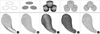
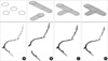
All structures were categorized into two groups, each of which needed different algorithm for surface reconstruction. In one group such as the gallbladder, neighboring outlines were overlapped (Fig. 2A). On the other hand, in the other group such as the hepatic artery, which usually consisted of many branches, neighboring outlines were not-overlapped (Fig. 3A, Table 1, 2).
Surface reconstruction of overlapped neighboring outlines
On AutoCAD, all stacked outlines of a structure were simultaneously packed by using 'region' command to acquire packed outlines model. It was a pre-process for the next procedure of volume reconstruction (Fig. 2B, Table 2).
On AutoCAD, all packed outlines were simultaneously extruded upon next ones by using 'extrude' command to make columns, which was the volume reconstruction. Additionally, all columns were combined by using 'combine' command to acquire columns volume model. If all columns were not combined, surface reconstruction could not be accomplished in the next procedure (Fig. 2C, Table 2).
On 3ds max, a surface of combined columns was extracted automatically by using 'cap closed objects' command, which was the surface reconstruction. The extracted surface, i.e., columns surface model, consisted of original outlines and triangular surfaces (Fig. 2D, Table 2).
On Maya, columns surface model was smoothed to acquire a smoothed surface model. The original outlines as well as the stairs in the columns surface model were automatically deleted by using 'smooth' command; during this procedure, the number of triangular surfaces was unintentionally increased. Intentionally, the triangular surfaces were appropriately reduced in number by using 'reduce' command. As a result, the triangular surfaces became close to regular ones (Fig. 2E, Table 2) (8).
On Maya, incorrect regions of the smoothed surface model, which were caused by incorrect segmentation, were manually corrected until the model corresponded to anatomical knowledge. After correction, the smoothed surface model was superimposed upon the previous outlines model to take a glance of correction. In the superimposed images, several regions of the smoothed surface model were either expanded larger than the outlines model, or shrunk smaller than the outlines model (Fig. 4A). In addition, the smoothed surface model was superimposed upon the serially sectioned images (Fig. 4B) (8).
Surface reconstruction of not-overlapped neighboring outlines
On Rhino, the structure, where neighboring outlines were not-overlapped, was divided into several branches. In each branch, all outlines were simultaneously connected with superoinferior lines by using 'loft' command. Additionally, the uppermost and lowermost outlines of each branch were closed by using 'cap planar holes' command to make disassembled surface models, which was the surface reconstruction (Fig. 3B, Table 2) (8).
Combination and division of surface models
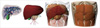
Forty-seven surface models were acquired by surface reconstruction of either overlapped neighboring outlines or not-overlapped neighboring outlines. By using 'color' tool on Maya, each surface model was colored as similarly as possible to the original color of the structures in serially sectioned images; for example, surface model of the liver was colored with brown. Otherwise, the surface models were colored by just following the convention; for example, surface models of arteries and veins were colored with red and blue (Fig. 5). In a Maya binary (MB) file, 47 layers were made to contain 47 surface models; each layer was named according to the name of structure, which followed Terminologia Anatomica (Table 1) (12). Surface model of each structure was placed on its own layer with preserving its own position to acquire combined surface models (Fig. 6, Table 2).
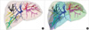
On Maya, a surface model of the portal vein was differently painted according to segmental branches. Among the portal triad in the liver, the portal vein was the thickest, therefore, many branches of the portal vein could be segmented and surface reconstructed. This was the reason of why we decided to use the portal vein branches for dividing a surface model of the liver into surface models of hepatic segments in the next procedure. The surface model of the portal vein and the semitransparent models of the liver, gallbladder, inferior vena cava, and hepatic vein were together observed at different angles. The portal vein bifurcated into left and right branches, between which the gallbladder, inferior vena cava, and intermediate hepatic vein were located. Subsequently, the left branch split into branches to hepatic segments I, II, III, and IV, while the right branch to hepatic segments V, VI, VII, and VIII. The branch to hepatic segment I was identified by the fact that hepatic segment I is the caudate lobe. Likewise, the branches to the other hepatic segments were identified; we just regarded the area of every hepatic segment in anatomy textbook (13). Therefore, there happened unexpected branches of the portal vein. For example, a branch bifurcated into a subbranch to hepatic segment V and another subbranch, which was the common trunk to hepatic segments V and VIII. After full identification, surface model of the portal vein was painted particularly according to segmental branches by using 'paint color' tool (Fig. 7A).
On Maya, a surface model of the liver was divided into surface models of hepatic segments referring to the painted portal vein. In surface model of the liver, borders between the neighboring hepatic segments were suitably drawn to intervene between neighboring segmental branches of the portal vein (14). Concurrently, border between hepatic segments II, III, and I, IV was drawn along the left hepatic vein; likewise, border between I, IV, and V, VIII along the intermediate hepatic vein; border between V, VIII, and VI, VII along the right hepatic vein. During this process, we found a variation that the left hepatic vein was thicker than the sum of the intermediate and right hepatic veins. After drawing the borders, surface model of the liver was separated into eight surface models by using 'sculpt geometry' tool (Fig. 7B, Table 2). In total, 47 surface models increased to be 55 models, and the eight new surface models were placed on the new eight layers of combined surface models. Additionally, both the hepatic artery and hepatic duct were differently painted according to hepatic segments.
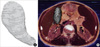
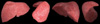
As the preliminary trial of volume reconstruction, both intervals and pixel size of serially sectioned images were increased from 0.2 mm to 1 mm; by the help of the segmented images, outside of the liver in all serially sectioned images were simultaneously erased on Photoshop. On 3D-Doctor software, the serially sectioned images were stacked and reconstructed by volume modeling to acquire a volume model of the liver with 1×1×1 µL voxels and real color. It was then rotated (Fig. 8).
RESULTS
The combined surface models included not only the liver structures but also the stomach, duodenum, muscles, bones, skin, and so on (Table 1). Each surface model was shown with its original shape and location preserved (Fig. 5, 6), because the outlines of structure were stacked with both horizontal-vertical ratio and proper location preserved (Fig. 1) (8). The surface models kept smoothed surface of the structures because medical experts drew outlines of structures (Fig. 1A) and carefully elaborated the surface models (Fig. 2E, 3D). Surface model of the liver was morphologically similar to the volume model (Fig. 8, 9), because both were created from the same origin of the serially sectioned images and segmented images. The result implied that the surface models, volume models, serially sectioned images, and segmented images could be superimposed on one another (Fig. 4B).
The combined surface models had small file size, because the models were yielded by surface reconstruction. Furthermore, the number of triangular surfaces in the surface models was reduced as much as possible without shape distortion of the structures (Fig. 2E, 3D) (15). As a result, the combined surface models could be conveniently handled in a real time.
On Maya, realistic surface models of the liver and neighboring structures could be displayed in many ways. Any combination of surface models could be selected to display by using layer window. The surface models could be shaded for stereoscopic effect by using 'hypershade' tool. In addition, color of individual surface model could be changed by using 'color' tool; we could make the color semitransparently to show other surface models behind (Fig. 6); the surface models could be rotated at arbitrary angles (Fig. 9). Moreover, if users want to see constitution of the surface model, the color could be replaced with triangular surfaces (Fig. 4B). These surface models could be displayed, rotated, and modified on three-dimensional popular commercial software such as AutoCAD, 3ds max, XSI, and Zbrush. Displaying and rotating were possible even on free software such as Autodesk Volo View3, Free DWG Viewer, where modification of the models was not permitted.
DISCUSSION
In the present study, we used popular software, excluding programming by the computer language. The popular software has a merit to enable any investigators to do segmentation and surface reconstruction without depending on computer programmers. Investigators can use various and user-friendly commands of the popular software without bug. Moreover, end users are able to open and modify the final results of surface models (MB file format) on their own popular software (16).
In this study, the surface reconstruction technique has been improved by trials and errors to find adequate commands of the popular software (Table 2). The increasingly automated technology saved time and effort of researchers to our satisfaction.
In our recent study, gaps between the stacked outlines were filled with surfaces by connecting outlines (8), and the procedure was performed with little automation extent, resulting in time consuming job. Essential point in the presently improved technique is that volume reconstruction is done prior to surface reconstruction. Volume reconstruction means that packed outlines are extruded upon next ones to make columns. Subsequently, all columns should be combined (Fig. 2C) for the next procedure, of surface reconstruction. The surface reconstruction means that a surface of the combined columns is extracted to acquire a surface model (Fig. 2D). Fortunately, both the volume and surface reconstructions can almost automatically be achieved on AutoCAD and 3ds max, respectively. In order to use the both software, the data have to be saved as DXF file, which can be shared by the both software (Table 2).
One of the drawbacks is that the improved surface reconstruction technique can be applied only to overlapped neighboring outlines. If neighboring outlines are not-overlapped, the extruded packed outlines, namely columns, are not attached to one another. Therefore, the columns cannot be combined, and a surface of the columns cannot be extracted either. In such case, the previous technique had to regretfully be used with low extent of automation (Fig. 3, Table 2). Possibly, the improved technique could be applied even to not-overlapped neighboring outlines, if intervening outlines, created by interpolation technique, could convert the not-overlapped to the overlapped. This trial appears to be challengeable because of minimization of time consuming work.
The not-overlapped neighboring outlines usually happen in the structures, which consist of many branches like the hepatic artery (Fig. 3A, Table 1). In the previous report, the structures were disassembled into dividing and not-dividing regions (8). However, in the present study, the structures were disassembled into several branches (Fig. 3B), which is strongly recommended because of more convenience of later assembling (Table 2).
In this study, we developed the technique to acquire surface models of structures with obscure boundary such as hepatic segments: based on the identified branches of the portal vein, we got eight surface models of hepatic segments from a surface model (Fig. 7B) (14). From this experience, we recognized that detailed surface models could be made either from serially sectioned images or from other surface model. It is obvious that detailed surface models can be acquired and verified only with anatomy awareness: in case of hepatic segments, surface models, acquired from the portal veins, can be verified from the hepatic veins. This technique to separate surface models into several ones can be applied to other structures with indistinct borders such as pulmonary segments.
In the present research, we have prepared 47 surface models of the liver and neighboring structures from serially sectioned images (Table 1). To our best knowledge, this is the first ever trial to obtain objective surface models of detailed structures inside and outside the liver. The surface models kept originality of location, horizontal-vertical proportion, and shape of the structures (Fig. 5, 6, 9). The surface models with small file size can be distributed, displayed, rotated, and modified in real time (9); and the manipulation can be accomplished without functional restriction on the popular software. One more advantage of the surface models made in this research is that they are accompanied by the serially sectioned images, which are the source of the surface models themselves. In other words, the surface models can be superimposed either upon the serially sectioned images (Fig. 4B) or upon the volume models (Fig. 8). This trial is valuable, especially when users need more information about the surface models.
The realistic surface models (MB file format) of the liver and neighboring structures, accompanied by serially sectioned images, will be distributed. The surface models are expected to promote interactive computer simulation such as virtual hepatic segmentectomy and virtual laparoscopic cholecystectomy for surgeons. The virtual hepatic segmentectomy can be done, based on the surface models of skin, abdominal muscles, hepatic segments, portal triad, and the hepatic vein (Fig. 5-7). Skin and abdominal muscles are cut to approach the liver. The liver is incised along borders between neighboring hepatic segments, where the hepatic vein exists; portal triads entering a hepatic segment is ligated to resect the segment (14). The virtual laparoscopic cholecystectomy can be done with the surface models of the skin, gallbladder, cystic duct, and portal triad (Fig. 6, 9). Skin is perforated to insert laparoscope into the peritoneal cavity. Using laparoscope's instruments, the cystic duct and cystic artery are ligated to resect the gallbladder; at this time, portal triad is carefully preserved, particularly the right hepatic artery (1).
From this research, we present the advanced technique of surface reconstruction as well as detailed surface models of liver and neighboring structures. The technique is hopefully reproduced by other investigators for creating their own surface models of other serial images. All VKH data, including sectioned images, segmented images, and surface models, are available free of charge for non-commercial applications. After obtaining permission to use data from the person responsible (currently, Sang-Ho Lee, Korea Institute of Science and Technology Information, Republic of Korea; shlee@kisti.re.kr), data will be provided to users worldwide either on- or off-line. The surface models are expected to encourage researchers to develop the virtual reality simulator of the abdomen contributing to clinical practice.


 XML Download