

 PDF
PDF ePub
ePub Citation
 Print
Print


Introduction
Percutaneous coronary intervention (PCI) has gained widespread acceptance as the treatment of choice for managing symptomatic coronary disease. The most important advance in the field of PCI was the introduction of coronary stent implantation in the 1990s because this lead to a reduction in both the risk of acute major complications and the incidence of restenosis, as compared with the risks after balloon angioplasty.1)2) While its technical success rate exceeds 95%, stent restenosis remains a clinical problem. The introduction of drug-eluting stents into clinical practice has dramatically reduced the occurrence of restenosis compared with the use of bare metal stents.3-5) Yet even at this low rate, stent restenosis remains an important problem,6-8) and so an efficient diagnostic tool for follow up after stent placement is needed. Coronary angiography is presently the standard procedure for assessing the vessel lumen after stent placement. However, this method may involve major complications due to its invasiveness.9) Therefore, the development of noninvasive and less expensive imaging modalities to assess the patency of coronary artery stents is of great clinical interest.
Magnetic resonance (MR) angiography also can depict the coronary anatomy and it can help to detect stenosis in the proximal segments of coronary arteries.10) However, metallic stents cause magnetic susceptibility artifacts that may prevent visualization of the lumen.11) Electron-beam computed tomography (CT) has been used to assess stent patency, yet assessment with this modality depends on indirect time-attenuation analysis in the vessel segments distal to the stent, but there is no actual visualization of the in-stent lumen.12)13)
Since its introduction, the multi-detector row CT (MDCT) technology for cardiac applications has continuously evolved. With increasing the number of detector rows, CT scanners can provide markedly improved temporal and spatial resolution on coronary imaging. MDCT also allows the imaging of coronary stents. There has been a dramatic increase in the number of recent investigations that have evaluated coronary stents by MDCT, and it is now valid to ask: Is this method ready for real world clinical use?
The purpose of this article is to review the current status and perspective of MDCT imaging of coronary artery stents.
Current Status
Multidetector CT scanners for the visualization of coronary stents
It is generally accepted that in-stent lumen evaluation using 4-slice MDCT is impossible.14-16) An in vitro study using 4-slice MDCT to assess 19 different stents showed that reliable lumen assessment was not feasible as blooming artifacts of the metallic stents obscured significant parts of the stent lumen in most products.14) The patient studies that used 4-slice MDCT for stent assessment were similarly disappointing.14-16) Therefore, contrast enhancement in the vessel distal to the stent has to date been the best criterion for stent patency.14-16) However, observing distal run-off cannot be considered an absolute indicator of patency as the presence of vessel enhancement distal to a stent can also be secondary to retrograde filling.
The introduction of 16-slice MDCT made CT a much more viable modality for detecting significant in-stent restenosis, with reported sensitivity and specificity values in the range of 54-100% and 88-100% respectively.17-23) Coronary artery stent patency has been assessed with using 16-slice MDCT scanners on the basis of contrast enhancement measurements18-22) or pixel count methods.23) However, for stents with small (<3 mm) diameters and/or thicker struts, visualization of in-stent stenosis remains a problem.17)20)21)
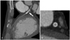
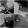
The recently introduced 64-slice MDCT scanners have improved both the temporal and spatial resolutions due to their reduced rotation time and thinner sections (0.6 mm). This modality is also likely to improve CT's ability to access stents (Fig. 1, 2). In an in vitro study, using 64-slice MDCT resulted in superior visualization of the stent lumen and in-stent stenosis compared with that of 16-slice MDCT, and especially when the stent is oriented parallel to the X-ray beam.24) The recently reported values for the sensitivity and specificity of detecting in-stent restenosis with using 64-slice MDCT are 89% and 95%, respectively.25) However, although 64-slice MDCT has allowed improved stent visualization, a relevant portion (up to 47%) of the stent lumen is still not assessable.26) There are many issues that interfere with the assessment of the real stent lumen, even with using 64-slice MDCT.
Issues interfering with stent assessment on Multi-detector-row CT
Mechanical factors (Beam hardening and the blooming effect, and the partial volume averaging effect)
Metallic stents cause a severe CT artifact known as the blooming effect; this is the result of beam hardening and it causes the stent struts to appear thicker than they really are.27) As a result the in-stent luminal diameter is underestimated. The energy spectrum of the X-ray beam increases as it passes through a hyperattenuating structure because lower-energy photons are absorbed more rapidly than are the higher-energy photons, resulting in the beam being more intense when it reaches the detectors. Calcified spots of the vessel wall near or at the outer surface of an implanted stent also contribute to beam hardening, which further erodes the assessability of the stent lumen.28) The magnitude of the artifact varies depending on the type of metal and the stent design.29) As a rule, the depiction of stents with the slimmest profile is least affected by blooming artifacts.28) Beam hardening artifacts also may be exacerbated by motion or by inappropriate selection of the reconstruction window.30) Conversely, blooming artifacts may be minimized by reduced motion and an optimal reconstruction window.28)30)
Another mechanical obstacle to coronary stent imaging is related to the partial volume averaging effect, and this is inherent in the cross-sectional imaging modalities and it yields a CT number that represents the average attenuation of the materials within the voxel. The partialvolume averaging may affect not only the measurement of the in-stent attenuation, but also that of the in-stent luminal diameter.29) As a result, the in-stent luminal diameters that are measured on the CT images are smaller than those measured on the conventional angiograms.22) The thin-section collimation of 64-slice MDCT and the high-resolution image post-processing algorithm help to decrease the effects of partial volume averaging.22)30-32)
Stent type
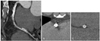
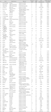
The visibility of different stents' lumens varies and this largely depends upon the stent type and the diameter. The blooming effect is more disturbing for smaller coronary stents with thicker struts (Fig. 3). Uninterpretable images tend to be obtained for stents with thicker struts and/or a smaller diameter. When the lumen diameter is less than 3mm, the lumen visibility is worse.21) Regarding the type of stent, the most severe artifacts are found with tantalum, gold or gold-coated stents, or with covered stent grafts as compared with stainless steel stents.33) Maintz et al.34) recently evaluated 68 different stents in vitro with using 64-slice MDCT and they created a catalogue of the CT appearance of most of the currently available coronary stents (Table 1). They confirmed that the high variability for stent lumen visibility depended on the stent type, and this was previously reported on with using 4-slice and 16-slice CT. They also concluded that while in vivo studies will be required to verify their results, it can be assumed that a reliable evaluation of stents' lumens in the more advantageous stent types, such as the Radius, Teneo, Symbiot or Flex standard stents, will be possible with using 64-slice MDCT.34)
Optimization of contrast enhancement
Optimal contrast enhancement is crucial for evaluating stent patency as well as for evaluating coronary arteries. The acquisition time also has a major impact on the quality of vascular contrast enhancement. There are three different bolus timing techniques: fixed delay, delay estimation from a test-bolus injection and real-time bolus-tracking. While the fixed delay technique has been practically abandoned for cardiac MDCT, the bolus-tracking technique is the most commonly used method. The test-bolus technique offers the theoretical advantage of being able to prospectively plan the shape of the time-attenuation curve. This approach has the potential to improve the homogeneity of the intravascular contrast and it also allows estimation of the functional parameters.35) A high degree of intraluminal enhancement is recommended, especially for the investigation of stent patency in vessels with a small diameter and thus they contain less blood.
Cardiac motion
Cardiac motion is one of the most important causes of vessel non-assessability on MDCT coronary angiography. The movement of coronary arteries results in blurring of the CT image and a smaller apparent stent lumen due to the partial volume effect and the metal blooming artifact. The use of high gantry rotation speeds and beta-blockers to lower the heart rate have consistently improved the interpretability of MDCT coronary angiograms.28) The use of multisegmental reconstruction (MSR) techniques could improve the image quality in patients with a high heart rate.36-38) However, Groen et al.39)40) recently reported that MSR showed no benefit of image quality for the visualization of coronary stents at high heart rates on a moving heart phantom with using 64-slice MDCT. They concluded that lowering of the heart rate is more beneficial for image quality than using a MSR technique. They also reported that in order to reduce blurring, it is more efficient to reduce the heart rate than to increase the temporal resolution.40)
Anatomical factors
The coronary arteries typically have an oblique course and they are often assessed from multiplanar reformats of the axial images. Therefore, all the stents are positioned at two different angles towards the z-axis of the MDCT scanner in order to simulate different scenarios regarding the spatial resolution along the z-axis.26) Mahnken et al.31) have investigated a small series of different stents at orientations of 0°, 45° and 90° toward the z-axis with using 16-slice CT, and they found that 0° was the most advantageous orientation. This may be the most likely orientation of a stent in the mid-segment of the right coronary artery. Stents in other vessels have decreased spatial resolution along the z-axis, which indicates that the assessable inner stent lumen is decreased. However, with the thinner slices of 64-slice CT, the orientation of 90° toward the z-axis could lead to better performance.24)
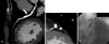
Another patient factor that might limit proper assessment of stent lumens, as well as the native coronary artery lumens, is severe calcification, and this should also be mentioned (Fig. 4). Ohnuki et al.23) evaluated coronary in-stent stenosis on 16-slice MDCT. Of the 20 lesions, two cases were misinterpreted due to calcification. Because of the calcification artifact, it is difficult to identify contrast in the lumen. Any calcification in the proximal portion of the left anterior descending artery is most likely to be severe and it is most influential on the assessability of the stents implanted in segment #6.21) However, as the severity and distribution of calcification are not uniform, these factors affect every stent in the other segments of the coronary arteries that have calcification and so this is considered to be one of the limitations of the currently available MDCT.
Perspective
How to overcome the limitations of Multidetector-row CT for the imaging of coronary stents
Dedicated edge-enhancing convolution kerne
Post-processing is an important part of lumen visualization of a coronary stent. An edge-enhancing, high-spatial-resolution kernel for reconstruction yields fewer blooming artifacts and less artificial lumen narrowing, and the intraluminal attenuation changes caused by such artifacts would therefore be minimized.41-44) Maintz et al.41) reported an average 23% increase in the visible lumen diameter and a mean reduction of the intraluminal attenuation of roughly 30% when they used the edge-enhancing, high-spatial resolution kernel (B45f convolutional kernel). Mahnken et al.42) found significantly smaller artificial lumen narrowing and lower intraluminal attenuation when they used a B45f convolutional kernel, as compared to the smoother B30f kernel. While the B45f convolution kernel is optimized to reduce the blooming artifacts that occur at the edges of structures that have high attenuation values, such as calcified plaques or metallic structures, a significant increase in image noise must be accepted as a trade-off, although this reduces the overall image quality and hampers the delineation of small low-contrast structures.41-44)
Stents
As was discussed above, the most severe artifacts are found with tantalum, gold or gold-coated stents, or with covered stents grafts as compared with stainless steel stents. Stents with lesser artifacts should be selected when follow up is planned. In the future, the development of CT transparent stents or biodegradable stents may create optimal conditions for non-invasive post-implantation follow-up with using MDCT.
Dual-source spiral CT
Residual cardiac motion has a role in increasing the metal-related artifacts such as beam hardening and partial volume averaging effects. Dual-source spiral CT (DSCT) provides a temporal resolution of 83 milliseconds (165 milliseconds on 64-slice MDCT). Lell et al.45) recently evaluated coronary stents and stenoses at different heart rates in vitro. They concluded that the depiction of coronary stents with DSCT is possible across a large range of simulated heart rates (50-120 bpm) without incurring motion artifacts. The overall measurement errors of the in-stent diameter with using DSCT were markedly smaller than those reported for 16-slice MDCT and they were smaller than those reported for 64-slice MDCT. Although larger clinical studies will be necessary to establish the accuracy of DSCT for assessing the degree of coronary artery stenosis in vivo, the preliminary results seems to be quite promising.
Conclusion
MDCT has recently emerged as a noninvasive method for evaluating coronary stents. Because of its presently limited sensitivity due to the various factors discussed above and because of its high radiation exposure, MDCT should not yet be used as a first-line test to screen for instent restenosis in asymptomatic patients. However given its high specificity and negative predictive value, MDCT might be valuable for confirming stent occlusion in symptomatic patients. Stent evaluation should focus on the proximal coronary artery segments and on stents with a diameter greater than 3 mm. Ideally the stent type should be known prior to the scan, as assessment of a particular type of stent can be predicted from in vitro-data. Larger clinical studies and further technical advances will be needed in the future to optimize the utility of MDCT for assessing the lumens in stents and in the coronary arteries.
 XML Download