

 PDF
PDF ePub
ePub Citation
 Print
Print


Abstract
Purpose
To determine the metal plate that has almost the same volume and weight as the conventional plate, but has improved properties by changing the shape using finite element analysis.
Materials and Methods
The bone is assumed to be of 100 mm length, 20 mm outer diameter and 12 mm inner diameter, respectively. There is a fracture line that is perpendicular to the major axis of the bone at the center. The two pieces of bone are joined together using a metallic plate that is made of titanium. Six holes are located, with an interval of 12 mm. We suppose that screws of 2 mm diameter and 25 mm length are inserted in six holes. The metallic plates are of 5 shapes (A, B, C, D and E) in total. Shape A is the standard or nominal type. Shape B and C are thicker at the center of the plate, respectively. Shape D and E are wider at the center. Six types of load are applied to each of those plates: tension, compression, anterior flexion, posterior flexion, lateral flexion and torsion. We compared stress, deformation, maximal stress and maximal deformation, according to the six types of load.
Results
Our deliberate investigation using finite element analysis showed that increasing the thickness or width at the center of metallic plates lowered the maximum stress and deformation. In particular, maximal stress and deformation could be reduced by 33.5% and 38.6%, respectively, in the anterior bending situation. Compression showed lower stress and deformation in type C or D, but the absolute quantity was much smaller than others, for example 0.01-0.001 times.
Figures and Tables

Figure 2
Stress and deformation distribution for anterior bending. (A) Load type: bending by +y directional force 10 N. (B) Stress distribution (unit: Pa). (C) Deformation distribution (unit: mm).
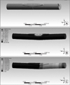
Figure 3
The graphs show maximum stresses according to the shapes of metal plates. (A) The stress peaks at torsional force. The thicker the middle of plate is, the smaller the stress is. (B) The stress peaks at torsional force. The wider the middle of plate is, the smaller the stress is.
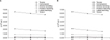
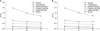
Figure 4
The graphs show maximum deforations according to the shapes of metal plates. (A) The deformation peaks at anterior bending force. The thicker the middle of plate is, the smaller the deformation is. (B) The deformation peaks at anterior bending force. The wider the middle of plate is, the smaller the deformation is.


References
1. Gardner MJ, Brophy RH, Campbell D, et al. The mechanical behavior of locking compression plates compared with dynamic compression plates in a cadaver radius model. J Orthop Trauma. 2005. 19:597–603.

2. Korner J, Diederichs G, Arzdorf M, et al. A biomechanical evaluation of methods of distal humerus fracture fixation using locking compression plates versus conventional reconstruction plates. J Orthop Trauma. 2004. 18:286–293.
3. Kowalski MJ, Schemitsch EH, Harrington RM, Chapman JR, Swiontkowski MF. A comparative biomechanical evaluation of a noncontacting plate and currently used devices for tibial fixation. J Trauma. 1996. 40:5–9.
4. Ferguson SJ, Wyss UP, Pichora DR. Finite element stress analysis of a hybrid fracture fixation plate. Med Eng Phys. 1996. 18:241–250.
5. Gautier E, Perren SM, Cordey J. Effect of plate position relative to bending direction on the rigidity of a plate osteosynthesis. A theoretical analysis. Injury. 2000. 31:Suppl 3. C14–C20.
6. Stoffel K, Dieter U, Stachowiak G, Gächter A, Kuster MS. Biomechanical testing of the LCP--how can stability in locked internal fixators be controlled? Injury. 2003. 34:Suppl 2. B11–B19.
7. Stoffel K, Stachowiak G, Forster T, Gächter A, Kuster M. Oblique screws at the plate ends increase the fixation strength in synthetic bone test medium. J Orthop Trauma. 2004. 18:611–616.
8. Woo SL, Lothringer KS, Akeson WH, et al. Less rigid internal fixation plates: historical perspectives and new concepts. J Orthop Res. 1984. 1:431–449.
9. Bucholz RW, Heckman JD, Court-Brown CM, Tornetta P, McQueen MM, Ricci WM. Rockwood and Green's fractures in adults. 2010. 7th ed. Philadelphia: Lippincott Williams & Wilkins;11–18.
10. Bucholz RW, Heckman JD, Court-Brown CM, Tornetta P, McQueen MM, Ricci WM. Rockwood and Green's fractures in adults. 2010. 7th ed. Philadelphia: Lippincott Williams & Wilkins;6–9.
11. Minns RJ, Bremble GR, Campbell J. A biomechanical study of internal fixation of the tibal shaft. J Biomech. 1977. 10:569–579.
 XML Download