

 PDF
PDF ePub
ePub Citation
 Print
Print


Abstract
Purpose
Materials and Methods
Results
Conclusion
Figures and Tables
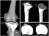 | Fig. 1The surface involving the transepicondylar axis is projected in the superior perspective of the tibial plateau and in the imaginary cut surface 10 mm below the lateral tibial plateau.
|
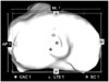 | Fig. 2Measured morphological parameters on the tibial plateau in the superior perspective. CAC 1, Canal axis center 1, is the location of intramedullary canal axis of the proximal tibia passing through the tibial plateau. LTS 1 is the location of the lateral tibial spine. SC 1, Surface center 1, is the anteroposterior and mediolateral center on the tibial plateau.
|
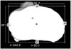 | Fig. 3Measured morphological parameters on the imaginary cut surface, 10 mm below the lateral tibial plateau in the superior perspective. CAC 2, Canal axis center 2, is the location of the intramedullary canal axis of the proximal tibia passing through an imaginary cut surface. SC 2, Surface center 2, is the anteroposterior and mediolateral center.
|
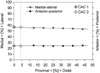 | Fig. 4Mathematically calculated canal axis center. The canal axis center was calculated using a least-squares fit to describe a line through the centroids.
|
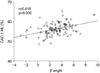
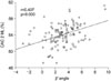
Table 1
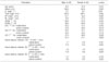
*β' angle, angle between the tibial anatomical axis and the line perpendicular line to the knee joint line; †AP length, Anteroposterior length of the tibial plateau in the superior perspective; ‡ML length, Mediolateral length of the tibial plateau in the superior perspective; §AP/ML 1, Anteroposterior length/mediolateral length of the tibia plateau in the superior perspective; ∥AP/ML 2, Anteroposterior length/mediolateral length, of the imaginary cut surface, 10 mm below the lateral tibial plateau; ¶CAC 1, Canal axis center 1, the location of the intramedullary canal axis of the proximal tibia passing through the tibial plateau; **CAC 2, Canal axis center 2, the location of the intramedullary canal axis of the proximal tibia passing through an imaginary cut surface, 10 mm below the lateral tibial plateau; ††LTS 1, Lateral tibial spine 1; ‡‡SC 1, Surface center 1, Anteroposterior and mediolateral center on the tibial plateau; §§SC 2, Surface center 2, Anteroposterior and mediolateral center on an imaginary cut surface, 10 mm below the lateral tibial plateau.
![]()
Table 2
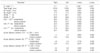
*β' angle, angle between the tibial anatomical axis and the line perpendicular line to the knee joint line; †AP length, Anteroposterior length of the tibial plateau in the superior perspective; ‡ML length, Mediolateral length of the tibial plateau in the superior perspective; §AP/ML 1, Anteroposterior length/mediolateral length of the tibia plateau in the superior perspective; ∥AP/ML 2, Anteroposterior length/mediolateral length, of the imaginary cut surface, 10 mm below the lateral tibial plateau; ¶CAC 1, Canal axis center 1, the location of the the intramedullary canal axis of the proximal tibia passing through the tibial plateau; **CAC 2, Canal axis center 2, the location of the intramedullary canal axis of the proximal tibia passing through an imaginary cut surface, 10 mm below the lateral tibial plateau; ††LTS 1, Lateral tibial spine 1; ‡‡SC 1, Surface center 1, Anteroposterior and mediolateral center on the tibial plateau; §§SC 2, Surface center 2, Anteroposterior and mediolateral center on an imaginary cut surface, 10 mm below the lateral tibial plateau.
![]()
 XML Download