

 PDF
PDF ePub
ePub Citation
 Print
Print


Abstract
Purpose
Tibial torsion is the external rotation of the distal tibia in comparison with the proximal tibia. Rotational deformity of the tibia as a complication of tibial shaft fracture means the loss of tibial torsion. Therefore, evaluating the torsion or the rotation of the distal tibia is the first step in reducing the rotational deformity of the tibia. There are two methods for evaluating the tibial torsion, a method with CT and a method with C-arm. In both methods, the anatomical landmark for evaluation is most important. The ratio of the tibiofibular overlap and fibula width (Tibiofibular Overlap Ratio) is a landmark commonly used to evaluate the tibial torsion.
Materials and Methods
The tibial torsion angle and Tibiofibular Overlap Ratio of both legs in 79 cases (48 males and 31 females; mean age 46.2 years) were measured and compared. These 79 cases received 2-D CT of the knee and ankle of both legs. To evaluate the prediction for neutral rotation of the tibia using the contralateral tibia-fibula image, 20 orthopedic residents and nurses were asked to select the same rotational tibia image among the 31 rotational 3-D CT images from 15° external rotation to 15° internal rotation in comparison with the mirror image.
Results
There was no significant between the comparisons of the tibia torsion angle and Tibio-fibular Overlap Ratio in both legs in the 79 cases. Ten orthopedic residents were able to predict the tibia rotational angle within an external rotation of 3° and internal rotation of 3°. Ten nurses were able to predict the tibia rotational angle within an external rotation of 5° and internal rotation of 5°.
Figures and Tables
Fig. 1
The method for measuring the tibial torsion. 2-D CT images of the distal femur and distal tibia are rotated using Photoshop version 6.0 to attain the neutral rotation images. Line A divides transverse axis of the patella and femur to the same length. Line B is perpendicular to the transmalleolar axis of the ankle. Angle C, which is made by the intersection of Line A and B, is the tibial torsion.
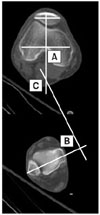
Fig. 2
The method for measuring the Tibiofibular Overlap Ratio. The fibular width is the distance A between the medial and lateral border of the fibula. The tibiofibular overlap is the distance B between the lateral border of tibia and the medial border of the fibula. B/A is the ratio of the tibiofibular overlap and fibular width.
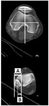
Fig. 3
(A) is the 3-D CT image of the 15° internal rotation view of the tibia. (B) is the 3-D CT image of 10° internal rotation view of the tibia. (C) is the 3-D CT image of 5° internal rotation view of the tibia. (D) is the 3-D CT image of 5° external rotation view of the tibia. (E) is the 3-D CT image of 10° external rotation view of the tibia. (F) is the 3-D CT image of 15° external rotation view of the tibia.
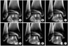
Fig. 4
The examiner selected the same rotational tibia image on the right-side monitor among 31 rotational 3-D CT images from 15° external rotation to 15° internal rotation in comparison with the mirror image on the left-side monitor.

Table 1
The Average and Standard Deviation (SD) of the Tibial Torsion and Tibiofibular Overlap Ratio of Both Legs in 79 Cases
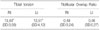
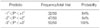
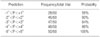
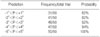
Table 2
The Results of the Prediction for the Tibial Rotation Angle in Comparison with the Neutral Rotation Mirror Image by the Orthopedic Residents
References
1. Clementz BG. Assessment of tibial torsion and rotational deformity with a new fluoroscopic technique. Clin Orthop Relat Res. 1989. 245:199–209.

2. Clementz BG, Magnusson A. Assessment of tibial torsion employing fluoroscopy, computed tomography and the cryosectioning technique. Acta Radiol. 1989. 30:75–80.
3. Eckhoff DG, Johnson KK. Three-dimensional computed tomography reconstruction of tibial torsion. Clin Orthop Relat Res. 1994. 302:42–46.
4. Hooper GJ, Keddell RG, Penny ID. Conservative management or closed nailing for tibial shaft fractures. J Bone Joint Surg Br. 1991. 73:83–85.
5. Jacob RP, Haertel M, Stussi E. Tibial torsion calculated by computerized tomography and compared to other methods of measurement. J Bone Joint Surg Br. 1980. 62:238–242.
6. Jend HH, Heller M, Dallek M, Schoettle H. Measurement of tibial torsion by computer tomography. Acta Radiol Diagn (Stockh). 1981. 22:271–276.
7. Kempf I, Grosse A, Abalo C. Locked intramedullary nailing. It application to femoral and tibial axial, rotational, lengthening, and shortening osteotomies. Clin Orthop Relat Res. 1986. 212:165–173.
8. Kyro A. Malunion after intramedullary nailing of tibial shaft fractures. Ann Chir Gynaecol. 1997. 86:56–64.
9. Matsushita T, Nakamura K, Okazaki H, Kurokawa T. A simple technique for correction of complicated tibial deformity including rotational deformity. Arch Orthop Trauma Surg. 1998. 117:259–261.
10. Prasad CV, Khalid M, McCarthy P, O'Sullivan ME. CT assessment of torsion following locked intramedullary nailing of tibial fractures. Injury. 1999. 30:467–470.
11. Sanders R, Anglen JO, Mark JB. Oblique osteotomy for the correction of tibial malunion. J Bone Joint Surg Am. 1995. 77:240–246.
12. Staheli LT, Engel GM. Tibial torsion: a method of assessment and a survey of normal children. Clin Orthop Relat Res. 1972. 86:183–186.
 XML Download