

 PDF
PDF ePub
ePub Citation
 Print
Print


INTRODUCTION
The resistance form of a fixed prosthodontic restoration has been defined in the Glossary of Prosthodontic Terms as “the features of a tooth preparation that enhance the stability of a restoration and resist dislodgement along an axis other than the path of placement.”1 The word “features” in the definition above relates two opposing walls and other adjuncts that contribute to the restoration's ability to resist rotational forces of dislodgement. A luting agent has been incorporated to assist these preparation attributes and oppose these forces that would act to dislodge the restoration from its position of physiological function during mastication.
The literature has demonstrated many factors that are related to resistance form: vertical wall angulation to the prepared tooth's long axis, wall height, finish line locations, total surface area, adjunct features, and surface texture. Much of the historical literature23456789101112131415161718192021222324252627282930313233343536 has proposed vertical wall angulation levels of the two opposing walls as convergence angles in the range of 6-to-12° total taper or 3-to-6° perwall (see Fig. 1). These citations234567891011121314151617181920212223242526272930313233343536 have proposed this standard as the ideal range to provide resistance to rotation of the restoration around a rotational axis.
In many of these citations, a fixed crown restoration was assumed to rotate around an axis located at the tooth-restoration interface at the restoration's margin or finish line. The vertical wall opposite from the rotational axis location has been thought to resist the rotation of the restoration away from the prepared tooth. The ability of this resisting wall to counter restoration rotation around this axis has been proposed to depend on the degree of taper from the vertical long axis of the tooth preparation. Parker et al.18 developed the concept of a maximum wall taper that would allow resistance to rotation around an axis referred to as “on” and “off” with “off” wall taper levels incapable of resisting this rotation.
As a result, once the maximal resistance taper level has been exceeded, the restoration rotational forces would be unopposed by preparation features with the entire rotational load transferred to the luting agent. A number of factors have been cited to influence this maximum allowable wall taper; theoretical calculations have shown that the larger the vertical wall height, the greater the maximum allowable wall taper is. In a classical review of the literature,7 the minimum wall height was determined to be 3.0-mm in premolars and 4.0-mm in molars with low levels of vertical wall angulations to be effective in posterior teeth with large force loads.
Another factor associated with the “on” versus “off” resistance form presence or lack of presence has been shown to be related to preparation surface area.35 Generally, as the axial wall angulation increases, the surface area of the preparation decreases as the preparation's four axial walls increasingly diverge from the long axis of the tooth or abutment. Thus, as preparation attributes proceed past the “on” minimal angulation to an unacceptable preparation with no resistance form in the “off” zone, the surface area of the preparation gets smaller. As a result, the luting agent has less surface area to utilize to stabilize the restoration or fixed partial denture to dislodging forces.
Two Finite Element Analysis (FEA) methodological studies2836 have demonstrated a different rotational resistance form of the tooth-restoration complex; the rotational axis in response to an external load condition has been shown to be at a different location compared to other studies. An experimental-occlusal load in both FEA model systems revealed a rotational axis location apical to the tooth-restoration complex, midway between the finish line and the apex of the tooth. These two studies have illustrated a bending of the tooth-restoration complex due to the differences between the modulus of elasticity of the restorative materials compared to the dentine tooth tissue.
Although base-width of the tooth preparation has been thought to influence resistance form in theoretical models, variation of base-width to a significantly larger distance from the axis of rotation to the opposite wall has not been experimentally assessed. The purpose of the present study is to determine the contribution of a wider base-width in an FPD compared to the resistance form of single tooth-sized fixed prosthodontic restorations. This study will investigate the base-widths greater than 9.0-mm (two previous investigations'3234 experimental, single-first molar had a 4.0-to-7.0 and 9.0-mm base-widths, respectively) as a variable within a 2-D, theoretical model system of an experimental fixed partial denture.
MATERIALS AND METHODS
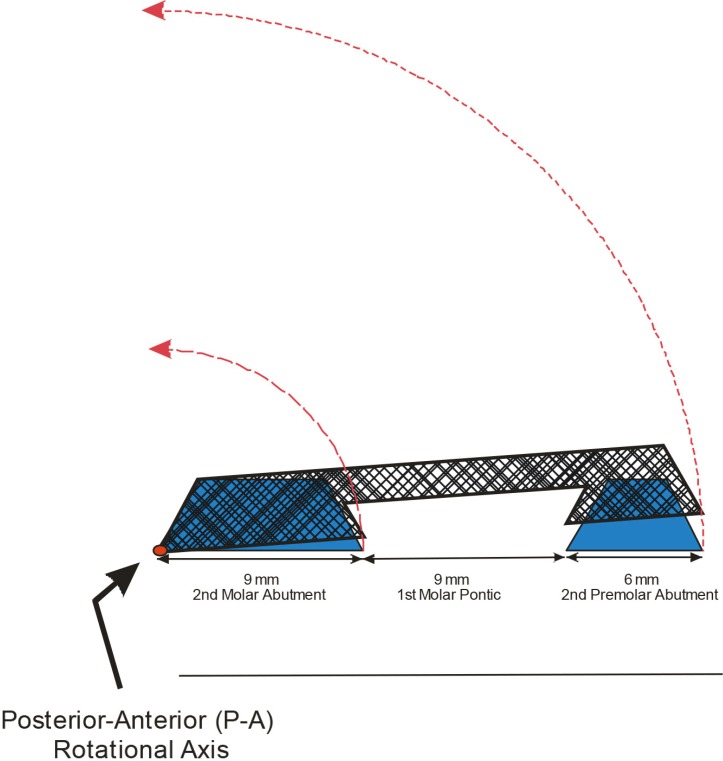
A two-dimensional experimental model system, 2-D in a single anterior-posterior, sagittal plane, consisted of a fixed partial denture with two posterior abutments and one pontic; the experimental-abutments were truncated triangles with the base lengths the size of a mandibular 2nd premolar and a mandibular 2nd molar with a mandibular first molarsized pontic. Both experimental-abutment preparations had two vertical walls, each with an occlusal surface; the entire experimental-FPD can be seen in Fig. 2 as a 2-D model in a single plane. The known vertical height [H (mm)] and horizontal base-width [B (mm)] in an anterior-posterior sagittal plane were utilized.
The experimental-abutment preparations' horizontal base-width dimensions were 6-mm 2nd premolar and 9-mm 2nd molar-sized abutments with 9-mm first molar-sized pontic to generate a total base-width of 24.0-mm. The model had five categories of abutment-preparation vertical height: 3.0-, 3.5-, 4.0-, 4.5-, and 5.0-mm. According to the literature,7 the 4.0-, 4.5-, and 5.0-mm abutment height categories are considered acceptable with the 3.0- and 3.5-mm categories considered unacceptable for the molar abutment. However, all height categories are considered acceptable for the premolar abutment. A series of trigonometric analyses were conducted to determine the maximal preparation taper needed to provide rotational resistance with variation of the abutment heights to resistance form factors.
The FPD in the experimental model was designed to rotate around two separate axes, one at the distal margin of the 2nd molar abutment at the tooth-restoration interface as the Anterior-Posterior (A-P) rotation axis as shown in Fig. 3 and the other at the mesial premolar abutment tooth-restoration interface as the Posterior-Anterior (P-A) rotation axis as shown in Fig. 4. First, these rotational manipulations were done in a series with both abutment heights at the same height, i.e., premolar abutment H3.5-mm paired with molar abutment H3.5-mm with similar pairings for the other three even abutment height categories, H4.0-, 4.5-, 5.0-mm.
Additional rotational manipulations in A-P and P-A axes were done in a series with uneven abutment heights; in the uneven abutment height rotations, the A-P and P-A axes were shortened in their vertical height locations. These rotational manipulations were done in the following combinations of A-P premolar and molar abutment heights for all abutment height combinations: H3.0-mm paired with molar abutment H3.5-, 4.0-, 4.5- & 5.0-mm, H3.5-mm paired with H4.0-, 4.5- & 5.0-mm, etc. Similar uneven abutment height combinations were analyzed for the P-A rotations with axis shortening at the mesial aspect of 2nd premolar abutment. The experimental model with A-P and P-A rotational axes in the uneven abutment heights can be seen in Fig. 4 and Fig. 5.
Rotational manipulation of the experimental-FPD around A-P and P-A axes resulted in four dependent variables as the maximal abutment wall taper necessary to provide resistance against rotation. The dependent variables, α (in degrees), were expressed as the maximal wall angulation from the vertical, long axis with manipulation of the FPD rotation around the A-P and P-A axes to provide resistance to rotation. α1 represented the maximal resistance wall angulation of the mesial axial wall of the 2nd premolar in the A-P axis rotation and the distal 2nd molar wall in the P-A axis rotation with both abutments at the same height. α2 represented the resulting resistance wall angulation of the mesial premolar wall in the A-P axis rotation and the distal 2nd molar wall in the P-A axis rotation with uneven abutment heights.
The two dependent variables α3 & 4 represented the maximal axial wall angulation (in degrees) required to resist rotation by the cross-tooth wall locations from the A-P and P-A rotational axes of the FPD's two abutments. The α3 A-P values represented the axial wall taper of the abutment wall opposite the rotational axis, the mesial wall of the molar abutment, with even abutment heights in the A-P rotation. The α3 P-A values represented the axial wall taper of the abutment wall opposite of the rotational axis, the distal wall of the premolar abutment, with even abutment heights in the P-A rotation.
The α4-values in both P-A & A-P the rotations were at the same resistance wall as α3 but the axis height was incrementally shortened. As the rotational axes were incrementally shortened in vertical height, the cross-tooth abutment resisting wall also shortened incrementally. Table 2 and Table 3 show the P-A & A-P α4-values with variation by shortening the axis height in 0.5-mm increments. All α1, 2, 3, & 4-values were determined by trigonometric calculations in five major steps; the formula derivations were reported in previous publications.183234 The formula ½ [Arc Sin (Hmm/Bmm)] allowed the calculation of the maximal taper angulation (expressed as α1 & 3-values in degrees) for resistance to prevent rotation of the restoration with the same vertical margin position on both abutment preparations. However, a manipulation of the vertical wall heights of one abutment compared to the other abutment would cause the rotational axis to shift to a more occlusal position. This shift of one margin to a more coronal location would produce a different arc of rotation of the margin of the taller abutment which requires lower angulation levels to produce resistance as can be seen in Fig. 4 and Fig. 5. An illustration of the P-A rotation of the premolar abutment H5.0-mm paired with the molar abutment H3.0-mm to produce the right triangle aef for the computation of the dependent variable, α2 in degrees, is shown in Fig. 6.
Two walls of one abutment were shortened to create the uneven abutment A-P and P-A pairings as described here: A-P premolar abutment H5.0-mm paired with molar abutment H3.5-, 4.0- & 4.5-mm, H4.5-mm paired with H3.5- & 4.0-mm, etc. (seen in Table 2); the P-A axis changes with molar & premolar pairings were similar (seen in Table 3). These combinations allowed for the calculation of α2 & 4 as dependent variables with the following formulas in steps (illustration of right triangles & trigonometric formulas can be seen in Fig. 6):
From right triangle abc, to compute radius ac of arc ae with ab = BTotal 24.0-mm as base-width and bc = H2-mm
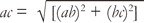
From right triangle cde, to compute side length de with ac = ce as radii of arc ae, rotation-center point c and cd = H4.5-, 4.0-, 3.5 & 3.0-mm
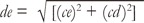
From right triangle aef, to compute α2 with ef = df - de and af = H5.0-mm
These 3 formulas were based on Pythagorean Theorem and trigonometric calculations with 2 known quantities to calculate a third unknown value.37
RESULTS
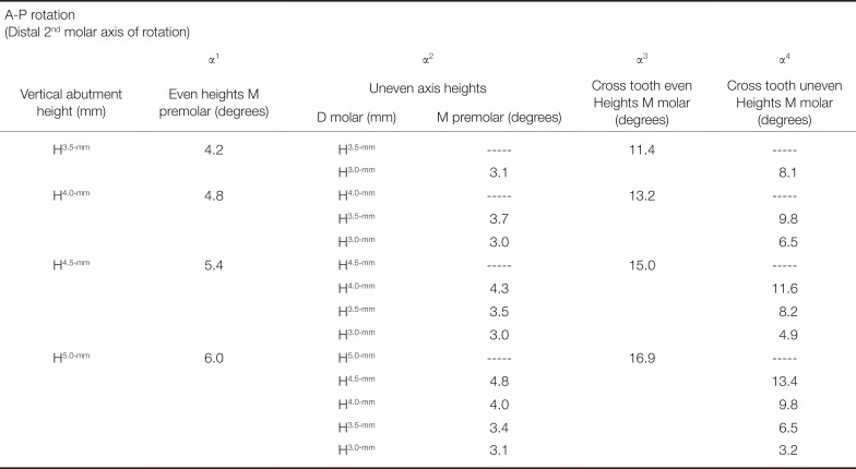
The A-P and P-A α1-values demonstrated the same resistance form values for all H3.5-, 4.0-, 4.5- & 5.0-mm-levels with even premolar & molar abutment heights; the same α1-values for A-P and P-A rotations were due to the same 24.0-mm FPD base lengths from both axes to the respective resisting wall in each direction. The two α1-values were related to the mesial wall of the premolar in the A-P rotation and the distal wall of the 2nd molar in the P-A rotation. The general trends of decreasing wall taper-values to offset decreasing abutment heights were evident.
The range for both A-P and P-A rotations with even abutment height levels demonstrated the lowest wall taper to resist rotation at 4.2° in the H3.5-mm abutment wall height compared to the highest levels needed at 6° with H5.0-mm abutment height levels. All other A-P and P-A abutment heights, H4.0- & 4.5-mm were midway between these two extremes of the range 4.2-to-6° with H4.0- & 4.5-mm = 4.8 & 5.4° respectively; all even abutment height levels in both A-P and P-A rotational manipulations demonstrated significance well below the 10°-level in this model (Table 1).
The α2-values from both A-P and P-A rotational axes with uneven abutment heights required less wall taper to maintain rotational resistance compared to the α1-values. The general trend revealed that shorter abutment heights and axis offset required even lower axial wall tapers for rotational resistance in the model. For example, A-P rotation with premolar abutment H5.0-mm paired with the molar axis shortened by 2-mm to a molar abutment H 3.0-mm represented the most extreme variation in the model and produced α2 = 3.1° compared to α1 = 6.0° for the same mesial wall of the premolar abutment in the even abutment height condition. The other three molar axis offset levels produced mid-range α2-values of 3.4, 4.0 & 4.8°, compared to the 3.1° & 6.0°extremes with 5.0-mm 2nd premolar abutment height. These same α2-values compared to α1-values in the P-A rotational manipulations demonstrated (Table 2) similar values as was seen the A-P rotations.
The α3 & 4-values represent additional resistance form in the FPD model system in many instances. The abutment wall opposite of the rotational axis on the same abutment provided additional resistance, sometimes at much greater wall tapers. For example, the mesial wall of the molar abutment on the opposite side of the A-P rotational axis provided cross tooth resistance with α3-values in the range of 11.4-to-16.9°. In addition, the distal premolar wall in the P-A rotational model provided additional resistance at greater taper α3-values in the range 15.0-to-28.2°. Both A-P and P-A types of α3 resistance form factors would supplement the overall FPD resistance form contributions of α1&2-values.
The α4-values in both the A-P and P-A rotations with cross tooth resistance to rotation demonstrated that lower axial wall angulations were needed, compared to the α3-values. In A-P rotation, the mesial axial wall of the molar abutment provides resistance. This wall angulation requires less wall tapers as the A-P axis location is shortened. The range for α4-values was 3.2-to-13.4° with the greatest effect seen in the 5.0-mm height abutment with axis vertical changes from 5.0-mm to 3.0-mm. In the P-A rotation, the distal wall of the premolar abutment provides the cross tooth rotational resistance. P-A α4-values had similar trends in the data with a range 4.9-to-21.8° as the axis was shortened on the mesial premolar location as can be seen in Table 3.
DISCUSSION
This investigation has demonstrated that longer base lengths in FPDs require lower axial wall angulations to maintain rotational resistance form compared to a single crown restoration with smaller base lengths. For example, from the data of the present investigation, H4.0 mm for both abutment heights of the FPD would require a maximum wall taper of 4.8° in the distal axial wall of the molar abutment to resist rotational displacement with 24.0-mm base width in the P-A rotational direction. However, smaller base sizes in the same molar abutment with mesial wall located cross tooth from the rotational axis in A-P direction with a smaller 9-mm base width has been found to allow a much greater taper angulation of α3 = 13.2°. The same phenomenon can be found in the FPD model with greater height abutments, H4.5 mm & H5.0 mm, for the same comparison, 5.4° vs. 15.0° and 6.0° vs. 16.9°. Discussions regarding the molar-size comparison utilized 4.0, 4.5 & 5.0 mm height abutments due to the minimum molar abutment height limitation of 4 mm recommended in the literature.7
In a similar comparison for the premolar abutment with a smaller abutment width of 6 mm, the base width issue shows an even greater impact; in this data comparison, the literature allows a shorter premolar abutment height of 3 mm as acceptable. This comparison generated the following pairings for the distant premolar 24 mm versus the 6 mm cross tooth situation from the FPD rotational axis: H3.0-mm 3.6° vs. 15.0°, H3.5-mm 4.2° vs. 17.8°, H4.0-mm 4.8° vs. 20.9°, H4.5-mm 5.4° vs. 24.3°, H5.0-mm 6.0° vs. 28.2°. As can be seen in the data, the effect of longer base lengths from the FPD rotational axis impact the axial wall a great deal as the clinician needs achieve very low angulations levels to offset rotational displacement of the prosthesis.
Thus, the data show significant differences between the two abutments sizes in this model system due to base lengths. Each abutment has different contributions to rotational resistance of each A-P and P-A rotation axes. The distal wall of the premolar and abutment resist the rotation around P-A axis and the mesial walls of the premolar and molar resist the rotation around the A-P axis. However, the distance from the rotational axis has a large impact on the angulation of the wall to resist rotation. Although single crown restorations were not included in this investigation, the principle of base length would also apply to these smaller restorations on posterior teeth; at the same tooth height, the premolar would be expected to require smaller wall taper opposite of the rotational axis compared to the molar.
Although the axial wall taper requirements have been shown to be different based on the distance from the rotational axis, the FPD restoration has the advantage of two axial walls resisting rotation about each rotational axis in both the A-P and P-A directions. The mesial wall of the premolar and the molar resist rotation in the A-P rotation, and the distal walls of the premolar and the molar resist rotation in the P-A rotation. One possible advantage in this restoration type, the FPD, is that rotational resistance may be present with only one of the two resistance walls at the lowest acceptable angulation or less levels. This effect may be a potent variable when the only rotational resistance wall is located at the most distant abutment from the axis of rotation. This may be an advantage compared to the single crown restoration with only one resistance wall.
A change in the vertical location of the rotational axis produced a change in the maximal axial wall angulation needed to resist rotation in the FPD model. A similar effect of uneven axis-finish line heights was shown in a previous study of single crown restorations.32 In general, the greater the change from the even abutment condition, the greater the change in the axial wall angulation is needed to offset rotational movement. For example, the largest vertical axis change in the FPD model, from 5 mm to 3 mm on the mesial aspect of the premolar abutment, occurred in a P-A axis vertical location. This maximal vertical location change resulted in the largest change in angulation needed to resist rotation by the distal, cross tooth axial wall of the premolar with 28.2° in the 5.0-mm condition compared to 4.9° needed for the 3.0-mm axis height condition. An axial wall difference of 23.3° would be needed to achieve the same level of minimal resistance form on the same abutment wall; a maximum of 28.2° in the 5.0-mm abutment compared to a more limited 4.9° axial wall in the 3.0-mm abutment condition for P-A rotation.
This study did not evaluate the effects of various related aspects cited in the literature: the contributions of surface area changes34 or mid-root rotational axis or modulus of elasticity within the tooth-restoration complex.2836 These factors may play a part in the rotational resistance form of an FPD, but they are not incorporated or considered in the present investigation. In addition, this investigation did not consider a buccal-lingual rotational axis in a second plane of space, the frontal plane, in this experimental FPD. Further investigation with a frontal plane and finite element analysis may be conducted in future studies of resistance form.
The current study did not investigate the effect of increased base lengths between abutments or increase numbers of abutments in this condition; the trend found in this investigation would indicate a tendency toward even more limitations on axial wall tapers as base lengths increase. However, the use of more abutments within a longer span FPD could increase the offset of axial wall angulations from one abutment to another deficient, distant abutment.
CONCLUSION
FPD abutment preparations must follow very strict guidelines to assure the resistance of the prosthesis to rotational dislodgement. The clinician should be aware of the six factors of resistance form in the FPD: two rotational axes, two distant axial walls, and two cross tooth abutment axial walls.


 XML Download