

 PDF
PDF ePub
ePub Citation
 Print
Print


INTRODUCTION
In the conventional impression technique, impression materials on a tray are used to take an impression of intraoral structures, after which model materials are poured on to obtain a working model. This impression technique has been established over hundreds of years and recognized as a method of fabricating an accurate restoration.1 However, in this conventional technique, the impression materials may cause discomfort and there is a risk of cross-infection. In addition, it may be impossible to take accurate simultaneous impressions in multiple sites according to the clinician's competence level due to the complexity of the impressiontaking process.2
In the digital-type impression technique, teeth are scanned with an intraoral scanner to produce an imaginary model on a monitor. Then the imaginary model is modified and its occlusion is checked, after which it is sent online to fabricate a working model using a computer-aided manufacturing (CAM) method. With this digital-type impression technique, the discomfort caused by impression materials decreases and the appropriate reduction amount can be determined immediately. In addition, it is easy to educate patients because the images of abutment formation are shown on the monitor. Moreover, the risk of cross-infection decreases, accurate raw data can be sent to the dental laboratory, and the data can be stored permanently.3
CEREC (Sirona Dental Co., GmbH, Bensheim, Germany), which was developed by Mörmann in Zurich University, is the world's first intraoral scanner. It was first used only for the fabrication of inlays and onlays, and its use has later been extended to the fabrication of crowns and fixed partial dentures.4 However, the digital-type impression technique using an intraoral scanner has not been widely used because it requires a private program for restoration, and an intraoral scanner and a milling machine. Accordingly, most clinicians use conventional impression techniques to take impressions and fabricate restorations. However, since the intraoral scanners such as iTero (Cadent Inc., Carlstadt, NJ, USA), LAVA COS (3M ESPE, St. Paul, MN, USA) and E4D Dentist (D4D Technologies, Richardson, TX, USA), which provide an open architecture for processing data using non-private programs, were introduced, the intraoral scanner has been reviewed.56
In CEREC, an active triangulation method with blue LEDs is used for intraoral scanning; in Lava COS, a 3D-inmotion technology with blue LEDs; and in E4D Dentist, a red laser technique. In iTero, images are obtained through the parallel confocal and telecentric principles. According to the parallel confocal principle, light that passes through a small pinhole is reflected after it contacts an object, and the reflected light again passes through the pinhole to be sensed by a sensor. In iTero, 100,000 rays of a parallel red laser beam are irradiated to an object to measure the distance through 300 layers of various depths for representing images without dental coating powder. According to the telecentric principle, the effects of the z axis are minimized by having only the light parallel to the light axis passing through an aperture installed on the lens focus. When objects have different depths, their image sizes may vary due to the difference in their distances; but according to the telecentric principle, the visual field of the scanned area can be evenly maintained regardless of the distance to the objects. Accordingly, it is unnecessary to further adjust the magnifying power for the contact scanning of the teeth. As a result, accurate images are more easily obtained with iTero than with other intraoral scanners.567
One of the important factors of the success of a fabricated restoration is marginal adaptation.8 Poor marginal adaptation can cause plaque accumulation, periodontitis, or dental caries, which may result in restoration failure.8910111213 In the cases of precious metal crowns, the theoretical marginal gap needed to achieve satisfactory marginal adaptation is 20-50 µm;14151617 however, considering the lifespan of the restoration, 100-200 µm is acceptable.18192021 Internal fit is another factor that must be considered when fabricating accurate restorations.22 To enhance internal fit, an appropriate and uniform cement space must be considered. When the cement space is excessive, the long-term stability can be compromised due to the dependence on the cement itself rather than on the tooth shape, and the direction can be lost while setting and cementing the restorations.23 On the other hand, insufficient cement space may cause incomplete setting of the restorations and reduce their retention.24
In a previous study on the marginal adaptation of restorations fabricated using the digital and conventional impression techniques,25 zirconia-based all-ceramic crowns that were fabricated using the computer-aided design /computer-aided manufacturing (CAD/CAM) system were used as restorations. Their suitability was affected by the information entering process, the software to compensate for the contraction errors that occurred during the sintering process, the accuracy of the cutting instruments, and the competence of the clinicians.262728 Therefore, it was difficult to evaluate the effects of the impression technique and the model preparation on the restoration suitability. Previous studies have reported the suitability of restorations fabricated using digital and conventional impression techniques, but few studies have been conducted that compared marginal adaptation with internal fit in artificial teeth and patient abutments.
In this study, the marginal and internal fit of precious metal crowns prepared with the digital impression technique using iTero was compared with the marginal and internal fit of precious metal crowns fabricated with the conventional impression technique using addition silicone impression materials in artificial teeth and patient abutments, to investigate the clinical usefulness of the digital impression technique.
MATERIALS AND METHODS
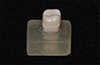
To fabricate cast gold crown, an artificial right maxillary first molar(Nissin Dental Prod. Inc., Tokyo, Japan) was prepared using a tapered round-ended diamond bur (TR 13; Mani Inc., Tochigi, Japan). A chamfer margin was prepared at the cementoenamel junction, and the axial plane was reduced by about 1.0 mm; the occlusal surface, by about 1.5 mm; and the axial inclination, by about 6 degrees. Finishing was conducted using a small grain-sized diamond bur (TR 13F & 13EF; Mani Inc., Tochigi, Japan) and a stone point (Shofu composite finishing kit; Shofu Inc., Kyoto, Japan). The root area of the prepared tooth was fixed to a 10mm-thick autopolymerizing acrylic resin (Orthoresin; Degudent, Hanau-Wolfgang, Germany) in the long-axis direction of the tooth to expose the lower end of the margin by 2 mm (Fig. 1).
The approval of the Institutional Review Board of Pusan National University Dental Hospital was obtained (Application No. N-2012-001-IIT). One prosthodontist performed all the procedures in this study. Of the patients who visited the Department of Prosthodontics of Pusan National University Dental Hospital, 10 patients (two males and eight females) who wanted cast gold crown were selected for this study. To minimize the patient factors, only one restoration was fabricated for each patient. Abutments were prepared for fabricating cast gold crown. After the tooth preparation, a temporary restoration was fabricated using polymethyl methacrylate resin (Tokuso Curefast; Tokuyama Dental Co., Tokyo, Japan) and cemented with Tempbond (Kerr, Romulus, MI, USA). An impression was taken one week after the tooth preparation.
For the conventional impression-taking, an individual tray was prepared. The tray was made 24 hours before taking the impression to prevent any error caused by the polymerization contraction of the tray resin. Inside the tray, an adhesive (Tray Adhesive Express, 3M ESPE, St. Paul, MN, USA) was evenly coated before the impression was taken using the addition silicone impression material (Imprint II Garant; 3M ESPE, St. Paul, MN, USA). Five minutes later, when the impression material had hardened, the impression body was removed and a gypsum cast was fabricated using an improved dental stone (Fujirock EP; GC Corp., Tokyo, Japan). Ten gypsum casts were formed using the same method (Fig. 2).
An individual tray was prepared for the conventional impression-taking. Before the impression was taken, a double gingival cord procedure was performed on the soft tissues in the abutment area. Gingival retraction cords (Ultrapak #000 & #0; Ultradent Prod. Inc., South Jordan, UT, USA) were used after they were soaked in aluminum chloride (Hemodent; Premier Dental Prod., Norristown, PA, USA). An impression was taken using an addition silicone impression material, and a gypsum cast was fabricated (Fig. 3). The impression of the antagonist tooth was taken using a typical metal tray (Frontier metal tray, Frontier Dental Industrial Co., Seoul, Korea) and alginate (Tokuyama AP-1, Tokuyama Dental Corp. Tokyo, Japan), and a gypsum cast was fabricated using a dental stone. The interocclusal record was taken using an addition silicone occlusal registration material (Futar D; Kettenbach GmbH, Eschenburg, Germany), and the gypsum cast was mounted at the semi-adjustable articulator (Hanau Modular Model 190-291111; Waterpik, Buffalo, NY, USA).
For the digital method, the impression of the artificial tooth was taken using iTero. The 45° occlusal, buccal, lingual, mesial, and distal planes of the tooth were scanned maximum 10 times. An imaginary model was formed using the scan data. After the imaginary model was evaluated, the data were transmitted to the iTero center for the fabrication of a polyurethane model (SikaBlock M1000; Sika Deutschland GmbH, Stuttgarter Str., Germany) using a five-axis computerized numerically controlled milling machine (VF-2TR; Hass Automatic Inc., Oxnard, USA). When the polyurethane models were fabricated, separate burs were used for each model. The process was repeated to prepare 10 polyurethane models (Fig. 4).
The soft tissues in the abutment area had been prepared before the impression was taken. The buccolingual, mesiodistal, and occlusal surfaces of the abutment were scanned five times using iTero, and the occlusal, buccal, and lingual surfaces of each tooth other than the abutment were scanned once to take impressions of them. Then the molar occlusion was scanned and recorded. After the imaginary model was evaluated, the data were sent to the iTero center for the fabrication of a polyurethane model (Fig. 5).
In each model, a die spacer (Nice Fit; Shofu Inc., Kyoto, Japan) was coated twice 1 mm superior to the margin to secure a cement space, and a die hardener (Stone Die & Plaster Hardener Resin; George Taub Prod. Fusion Co. Inc., Jersey City, NJ, USA) was coated inferior to the margin. Following the typical method, a wax pattern was prepared, and 40 cast gold crowns (Type IV gold alloy C-55; Shinhung Dental Gold Alloy, Seoul, Korea) were prepared (Fig. 6) using the conventional casting method. One dental technician performed these procedures.
The cast gold crowns that were fabricated using the conventional impression technique were assigned to the conventional group, and those fabricated using the digital impression technique, to the digital group.
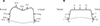
After the cast gold crowns were filled with light body addition silicone (Aquasil Ultra XLV; Dentsply-Caulk, Milford, CT, USA), they were positioned on the teeth. To implement the clinical luting restoration process, maximum finger pressure was applied. After the silicone hardened, the cast gold crowns were removed from the teeth. Regular body addition silicone (Aquasil Ultra LV; Dentsply-Caulk, Milford, DE, USA) was injected inside the crowns and hardened to stabilize the thin silicone film. After the silicone replica was cut at the buccolingual midpoint and the mesiodistal trisection point using a sharp razor blade (Fig. 7), the measurement points (marginal, marginal-axial plane transition, center of the axial plane, and occlusal surface quadrisection points) were determined (Fig. 8) to measure the width of the gap between the teeth and the restoration. The absolute marginal discrepancy (Fig. 8. A, I, a, i, 1, and 9), which is the distance between the restoration margin and the abutment margin, and the internal marginal gap (Fig. 8. B, H, b, h, 2, and 8), which is the perpendicular distance between the restoration and the tooth surface in the marginal-axial plane transition area, were measured to evaluate the marginal adaptation. The internal fit was evaluated by measuring the perpendicular distance between the inner wall of the restoration and the tooth and measuring the internal gap width (internal gap), on the axial plane (Fig. 8. C, G, c, g, 3, and 7) and on the occlusal surface (Fig. 8. D, E, F, d, e, f, 4, 5, and 6). After photos were taken using a microscope (Olympus BX 51; Olympus, Tokyo, Japan) at 100× magnification and a digital camera (Polaroid DMC2 digital microscope camera; Polaroid Co., Cambridge, MA, USA), the gap width was measured using I Solution (IMT i-Solution ver. 10.1; IMT i-Solution Inc., Dajeon, Korea) (Fig. 9). A trained experimenter measured each area thrice, and the mean values were recorded.
The mean and SD of the margin and the internal gap width between the cast gold crown and the tooth surface were calculated. The Kolmogorov-Smirnova test and the Shapiro-Wilk test were used as the normality tests for the impression techniques. When the normality was satisfactory, the t-test was used; otherwise, Wilcoxon's Signed Rank test was used. To test the difference among the measurement points in the impression techniques, ANOVA (one-way analysis of variance) was used. As an ad hoc test, Tukey's HSD test was used. All the statistical treatments were tested at a 95% confidence level.
RESULTS
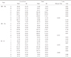
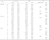
The mean and SD of the digital group and the conventional group are shown in Table 1 and Table 2. The mean of the gap widths at all the measurement points was defined as the “mean gap width.” The mean gap widths of the digital group and the conventional group are shown in Table 3. The mean gap width was in a clinically acceptable range, and that of the digital group was significantly greater than that of the conventional group (P < .05).
The statistical analyses significant differences were observed in measurement points C, D, E, F, e, f, h, 4, 5, and 6 of the master models (P < .05) (Table 1); and in the patients, measurement points D, E, F, d, e, f, 1, 4, 5, and 6 (P < .05) (Table 2).
In the marginal adaptation, no significant difference was observed (P > .05). The analyses of the absolute marginal discrepancy and the internal marginal gap in the master model showed that the internal marginal gap of the digital group was significantly less than that of the conventional group (P < .05) (Table 4).
The internal fit of the digital group was significantly greater than that of the conventional group (P < .05). The analyses of the axial surface and the occlusal surface showed no difference in the gap width on the internal axial surface (P > .05), but a significantly greater gap width on the internal occlusal surface in the digital group than in the conventional group (P < .05) (Table 5).
Significant differences were observed among the measurement points in the impression techniques (P < .05) (Table 6). In the conventional group, the master model showed a significantly smaller gap width in the margin than the patient in the axial surface. Both the master model and the patients showed significantly greater gap widths on the occlusal surface (P < .05). In the digital group, both the master model and the patients showed significantly less gap widths in the margin and the axial surface than on the occlusal surface (P < .05).
The gap widths measured in the artificial tooth and the patient abutments showed a similar tendency. However, the mesiodistal section analysis (P < .05) showed that unlike in the master model, the absolute marginal discrepancy and the internal axial surface gap width in the digital group patient were significantly less than those in the conventional group patients (Table 7).
DISCUSSION
Restorations should obtain accurate marginal fit, structural rigidity, and intraoral stability with the harmony between their functions and esthetics. Marginal adaptation is particularly important for the long-term success of a restoration.8 Poor marginal adaptation of a restoration results in an increase in plaque and food deposition, and in gingival tissue inflammation and dental caries, which reduce the lifespan of the restoration.8910111213 Internal fit is important in the fabrication of accurate restorations.22 An appropriate and uniform cement space is required to enhance the internal fit. When the cement space is excessive, retention depends more on the cement than with the tooth, which decreases the long-term stability.23 When the cement space is not enough, the restoration is incompletely seated, which hinders the retention.24 In the clinical application of a restoration, evaluations of the marginal and internal fit are required, and the evaluation standards such as the measurement methods, number of measurement points for significance, and measurement criteria must be considered.
Extracted human teeth show changes in their physical properties according to their storage condition and the lapsed time after their extraction, which make it difficult to maintain the uniformity of the sample. In addition, it is impossible to obtain multiple samples from a single patient.2930 Therefore, in most margin measurement studies, artificial teeth are used instead of natural teeth, and one master model is reproduced into multiple samples before their marginal gaps are measured. In this study, an artificial tooth was used to evaluate the difference between the impression techniques. Through model experiments, research conditions such as the tooth preparation, impression-taking method, and experiment process can be uniformly obtained, whereas through clinical trials, various clinical manifestations can be included and realistic evaluations can be made.26 In this study, both the model experiments using an artificial tooth and the clinical trials using the patients' intraoral abutments were conducted.
Commonly used restorations include cast gold crowns, porcelain fused gold crowns, and zirconia-based all-ceramic crowns. Porcelain fused gold crowns, which are made of a gold alloy, have good fit due to their metal coping fabrication, but require a multi-step ceramic-plasticity process that has been reported to have caused transformations in the metal coping and ceramics during the preparation process and have degraded their fit.3132 Zirconia-based all-ceramic crowns show a wide variation in suitability due to the errors in the abutment-form scan, coping fabrication, and zirconia processing processes, the contraction in the zirconia sintering process, and the differences in the levels of competence of the clinicians.262728 Cast gold crowns have been known to have the best fit among restorations due to their excellent castability and adhesiveness as gold alloys.1617 In this study, cast gold crowns were selected as the experimental restorations. To exclude the subjective factors of the dental technician, only one dental technician who was experienced in fabricating cast restorations conducted the experiments.
The factors that affect the fit include the cement space, the pressure generated during the cementation, and the margin shapes.33 Appropriate cement space is required to achieve excellent suitability. The cement space reduces the initial-stage hydraulic pressure during the cementation process and increases the cement distribution effect with minimal frictional resistance to accomplish perfect seating of the restoration.3334 According to Gardner35 the cement thickness increased by up to 100 µm when the hydraulic pressure was not reduced. The methods of reducing the hydraulic pressure include venting and internal relief.3637 Internal relief can be attained through internal reductions of the wax pattern and the framework, the internal etching process of the framework, the electrochemical milling process, and die spacer coating.8 In this study, the die spacer was coated to provide the restoration with a space.
A previous study reported that there was no correlation between the cementation pressure and the fit,38 but the cementation pressure is a major factor that affects the marginal adaptation.39 In most model experiments, devices such as universal testers, which can produce a uniform force, are used to prevent any change in the fit during the restoration cementation process.40 However, in this study, the model experiments and clinical trials were conducted in the same condition. To simulate the restoration cementation process in the clinical setting, finger pressure was applied to the restoration.
A previous study reported that there was no correlation between the margin form and the suitability.41 Regarding the effect of the margin form on the suitability, Pera et al.42 compared the margin adaptation in the chamfer, and the 50° shoulder and 90° shoulder margins using a stereomicroscope. A 50 µm or less marginal adaptation was observed in all the clinical cases regardless of the reduction form, but the chamfer and the 50° shoulder margin showed better marginal adaptation than the 90° shoulder margin. Based on these conclusions, the chamfer margin was adapted in this study.
The experimental methods of measuring marginal fit include direct measurement, sectional measurement, evaluation through impression-taking, evaluation through probing, and simulation method.43 Through the microscopic observation method, repeated measurements are available and additional measurement sites can be chosen, but the measurements may be inaccurate.43 The methods using impression taking and probing is inaccurate.4445 Moon et al.44 reported that the sectional measurement method is the most accurate method, but in such method, it is difficult to increase the number of measurement sites; to do so, additional samples are needed. According to Leong et al.,45 sectioning metal preparations could deform the margin. Therefore, Molin and Karlsson used the replica technique on restoration margin fit in the comparative study.46 This method is simple because the restorations do not need to be sectioned, the margin deformity during sectioning can be prevented, the number of the measurement sites can be easily increased, and repeated measurements are available.46 In addition, the marginal and internal fit can be accurately measured. This method is also ethically acceptable for use in a marginal fit study that targets patients.47 Accuracy of the replica technique have been known to have been low, but it is now widely used to measure the accuracy of restorations because materials with enhanced accuracy such as addition silicone are used. According to Rahmé et al.,48 there was no significant difference in accuracy between the conventional method of sectioning the restoration and the replica technique. In this study, the marginal fit of restoration was measured using the replica technique.
In measuring the gap width between a tooth and a restoration, the number of measurement points must be considered. The use of few measurement points is convenient and fast, but the deviation according to the measurement site increases; on the other hand, the use of many measurement points can provide reliable results, but it is time-consuming. To calculate a representative value of the marginal fit of a sample, an appropriate measurement number is required. Nevertheless, no appropriate measurement number for the significance of the restoration suitability has been reported yet. In the gap analysis of a single crown, Gassino et al.49 measured minimum 18 times, and Groten et al.50 did more than 50 times. In the fixed abutment measurement, Yoon et al.51 measured each of 8 measurement points thrice (a total of 24 measurements); Vigolo and Fonzi52 measured each of 8 measurement points once (total: 8 measurements); and Gonzalo et al.53 measured each of 4 measurement points 30 times (total: 120 measurements). In this study, 9 measurement points on each of three sectional planes were measured three times.
The standards for measuring restoration marginal fit have been defined in many studies. Holmes et al.54 defined the perpendicular distance between the axial plane of an abutment and the internal surface of a restoration as the “internal gap”, and particularly, they called the distance from the marginal area to the internal surface of the restoration the “marginal gap”. According to them, since the absolute marginal discrepancy, which is the distance between the abutment margin and the restoration margin, was the greatest among the marginal errors, the discrepancy was suggested as a clinically useful standard. In this study, the internal marginal gap between the absolute marginal errors and the marginal-axial plane transition was measured in the marginal area, and the internal gap was evaluated by measuring the perpendicular distance between the abutment axial plane and the internal surface of the restoration on the axial plane and the occlusal surface.
The outcomes of these measurements must be evaluated with respect to clinical acceptance. Previous studies have reported the range of the clinically acceptable marginal gap. The American Dental Association (ADA)14 determined the clinically acceptable range as 25 - 40 µm in ADA Specification #8. Sorensen et al.15 suggested a 50 µm or less marginal gap for inhibiting bone loss caused by marginal errors, and Christensen16 suggested an appropriate marginal gap of 40 µm. Ostlund17 suggested a less than 50 µm level. In the case of restorations using the conventional casting method, a 50 µm or less marginal gap was realized in the optimal condition. Nevertheless, according to Moon et al.,44 marginal fit is merely a standard for experiments, and it cannot be a standard for clinically acceptable margins. In the study of McLean and von Fraunhofer18 the marginal gap of 80 µm or less was hardly detectable with radiologic methods, and a 200 µm gap width was undetectable even with a 80 µm probe. They investigated 1,000 intraoral restorations that were used for more than five years and confirmed that a 100 µm marginal discrepancy was clinically not a problem, so they suggested 160 µm as a clinically acceptable marginal gap. Gulker20 confirmed that a gap of up to 200 µm is clinically acceptable. From the study of Kydd et al.21 on the marginal leakage in teeth extracted due to periodontal diseases, they reported that the restorations could be used for more than 20 years with the margin with a 74 µm cement thickness, 432 µm leakage, and 244 µm marginal gap. Therefore, the marginal suitability may be clinically acceptable with the maximum 200 µm marginal gap in the 100-200 µm range. In this study, the mean gap width and the marginal gap of the metal crowns were within the clinically acceptable range in both groups. These results correspond with those of Syrek et al.25
The internal gap width affects the retention of restorations. Jørgensen and Esbensen55 confirmed a moderate effect of a 20-140 µm difference in the cement thickness on the retention and observed a significant decrease in the retention only in the cases of a 140 µm or greater difference. Passon et al.56 reported no change in the metal crown retention with a 151 µm-thick cement. In this study, only the conventional group showed a clinically acceptable internal fit in the model experiments, consistent with the results of previous studies. In the case of single molar crowns, the internal axial plane gap width more significantly affected the restoration retention than any other internal gap width, and the evaluation of the internal axial plane gap widths in both groups showed that they were both clinically acceptable.
The wide internal gap width was mainly caused by the wide internal occlusal surface gap width. In this study, the gap width was greater than the gap widths in previous studies. This was deemed to have been due to the finger pressure applied to the restoration for its seating on the tooth in the gap width measurement using the replica technique. The luting pressure is an important factor that affects the marginal adaptation.39 In the model experiments, devices such as a universal tester were used; in other clinical studies, a device that could apply a 50 N even force to the restoration was used.26 Since this force could not be realized with finger pressure, the gap width in this study was greater than those in previous studies. Although the marginal gap was in the clinically acceptable range, the measured gap width was greater than those of previous studies, which was deemed to have been due to the lack of luting pressure that caused incomplete seating of the restoration on the tooth.
However, the internal occlusal surface gap width in the digital group was significantly greater than that in the conventional group. Considering that the digital group showed a slightly smaller internal axial plane gap width than the conventional group, the restoration of the digital group was not completely seated due to its smaller internal axial plane gap width. In this case, the marginal gap of the digital group should have been observed to have been greater than that of the conventional group, but the marginal gap did not show a significant difference among the impression techniques. iTero is based on the telecentric principle with an aperture at the lens focus through which only the light parallel to the light axis passes.567 Although iTero could minimize the z axis effects compared with other intraoral scanners,7 its perpendicular marginal fitness was insufficient compared with the conventional impression technique.
In both the model experiment and clinical trials, the internal marginal gap was observed to have been greater than the absolute marginal errors. Based on the internal occlusal surface gap width in the digital group, which was significantly greater than that in the conventional group, the digital group was considered perpendicularly greater than the conventional group. This meant that the digital group showed a closer contact with the abutment in the internal axial plane than the conventional group. Accordingly, the digital group should have had more absolute marginal errors than the conventional group, but the internal marginal gap was observed to have been greater than the absolute marginal errors in this study. This result might have been due to the factors associated with laboratory work and with the error corrections in the marginal area finishing process. To verify this assumption, the restoration retention may be measured. Since the restoration retention is enhanced with better marginal fit in the axial plane of the same abutment, the retention in the conventional group might have been lower than that in the digital group if the assumption was correct. Further studies may be needed.
In the model experiments, no significant difference in the margin and internal axial plane gap widths was observed among different impression techniques. However, in the clinical trials, no significant difference in the absolute marginal errors and the internal axial plane gap width was observed in the buccolingual direction. On the other hand, in the mesiodistal direction, a greater gap width was observed in the conventional group than in the digital group. The addition silicone impression material must be 2 mm thick for volume stability.57 In the model experiments, individual trays were prepared for the 2 mm uniform impression material spaces given to all the tooth surfaces. The individual trays were prepared in the clinical trials; a uniform impression material space was given to the buccolingual direction, but could not be given to the mesiodistal direction due to the adjacent teeth. Moreover, since the nearby impression body that was not supported by the tray while the impression body was removed from the oral cavity was removed through the maximum bulging area of the nearby tooth, a deformity could have developed during removal, had the minimal thickness for volume stability not been secured. As a result, in the clinical trials, the mesiodistal absolute marginal errors and internal axial plane gap width in the digital group were observed to have been greater than those of the conventional group. To enhance the clinical validity, the adjacent teeth may need to be considered in the model experiment planning stage.
In this study, the stability of the precious metal crowns that were prepared using the digital impression technique was compared with that using the conventional impression technique. The comparison of the marginal fit of the artificial teeth and the patient abutment using the replica technique showed that the precious metal crowns that were prepared using either impression technique had clinically acceptable marginal fit. However, Kunii et al.58 reported that the larger the restoration was, the more inaccurate it was. Further studies on the restoration length, the length of the edentulous area, and the forms and shapes of the restoration may be needed.
CONCLUSION
In this study, the marginal and internal fit values of precious metal crowns that were prepared using the digital and conventional impression techniques in an artificial tooth and patient abutments were compared.
Both prostheses presented clinically acceptable results with comparing the fit. The prostheses fabricated from the digital impression technique showed more gaps, in respect of occlusal surface.


 XML Download