

 PDF
PDF ePub
ePub Citation
 Print
Print


INTRODUCTION
Metal-ceramic crowns, which consist of a thin metal coping bonded onto abutment teeth and a fused ceramic layer on top, are widely used for fabricating dental restorations.1
Although precious metal alloys have been used as the primary materials for dental restorations, the rising cost of such materials and the increasing concern amongst patients regarding the expense of dental prosthodontic treatment has encouraged the development of new dental alloys. Nickel-chromium (Ni-Cr) alloys have been highly favored for use in metal-ceramic crowns. However, despite their high popularity, they have exhibited inherent limitations with regards to the formation of excessive oxides and bioincompatibility that has led to allergic reactions in some patients. Therefore, cobalt-chromium (Co-Cr) alloys have been suggested as novel alternatives because of their high mechanical strength, corrosion resistance, biocompatibility, and cost efficiency.1,2,3
Non-precious dental alloys have been used in conjunction with conventional lost-wax casting techniques to fabricate restorations; this has subsequently evolved into methods applicable to automated processing. The adoption of automated systems has in turn facilitated the development of a diverse range of fabrication methods, including the computer-aided milling and direct metal laser sintering (DMLS) systems. The computer-aided milling involves mechanical processing of restorations by subtracting prefabricated blanks, while the DMLS incorporates an additive manufacturing (AM) system that fabricates restorations by applying a laser, which selectively melts a metal powder to build up layers of solidified material.4,5,6 This additive method, also known as selective laser sintering (SLS), has drawn particular attention owing to its capability of preventing distortion and fabrication defects that inherent to conventional fabrication methods.7
Ultimately, the marginal and internal fit of a dental restoration provides the overarching factors for its success and longevity.8 For instance, a superior marginal fit markedly reduces the recurrence of dental caries and development of periodontal diseases, and extends the longevity of the restoration.9 Furthermore, a superior internal fit is necessary to maintain and support restorations.10
Although numerous metal-ceramic crowns are being widely used clinically, these are typically fabricated by conventional means from Ni-Cr alloys, and this was the focus of most previous studies.11,12,13 Thus, very few studies have provided a comparative assessment of metal copings based on Co-Cr alloys with regards to their marginal and internal fits. Therefore, Co-Cr alloy copings for metal-ceramic crowns were fabricated as part of this study using the latest computer-aided milling and DMLS. Comparative samples were also produced by a conventional lost-wax casting method to verify the extent to which the marginal and internal gaps vary in relation to the fabrication method, as well as to ascertain whether such gaps fall within the range of clinical acceptance. A null hypothesis is established that "the marginal and internal gaps of restorations will not vary with different fabrication methods."
MATERIALS AND METHODS
This study selected a maxillary right canine from a typodont resin model (AG-3; Frasaco GmbH, Tettnang, Germany). The selected resin tooth was prepared with a 1.0 mm circumferential chamfer finishing line, an incisal height reduction of 1.5 mm and a 6° axial inclination. Finally, all sharp edges were rounded off.
To make a stone replica, the resin abutment tooth was first replicated in silicone (Deguform®; DeguDent GmbH, Hanau-Wolfgang, Germany). A type IV stone (GC Fujirock EP; GC Europe N.V., Leuven, Belgium) was then poured into this silicone mold to fabricate a total of 30 working models, i.e., 10 models per group.
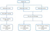
To give some internal space for cementation, a die spacer (Space-It; George Taub Products, Jersey City, NJ, USA) was first applied to the 1 mm upper margin of the abutment teeth working model to a thickness of 25 µm.14 A dipping method was then used to fabricate a 0.5 mm thick wax pattern. Next, a plastic sprue was attached to the completed wax coping, which was followed by investing and burn-out. To ensure a stable casting of the Co-Cr alloys (StarLoy C; DeguDent GmbH, Hanau-Wolfgang, Germany) (Table 1), a high-frequency casting machine (Fornax® T; Bego, Bremen, Germany) was used (Fig. 1); the investing, burn-out and casting processes were conducted in compliance with the manufacturers' instructions.
Ten working models were scanned with a 3D laser scanner (D800; 3Shape A/S, Copenhagen, Denmark). The models were then used to design the copings using a CAD software program (Dental DesignerTM; 3Shape A/S, Copenhagen, Denmark). As in the casting, the thickness was 0.5 mm and an internal space of 25 µm was provided from the 1 mm upper margin. The data relevant to the completed design was saved as an STL file, which was in turn fed into a milling machine (Datron D5; Datron AG, Mühltal, Germany). Metal blanks (KERA®-DISC; Eisen-bacher dentalwaren ED GmbH, Rhine-Main, Germany) (Table 1) were then milled to fabricate the Co-Cr alloy copings (Fig. 1).
In order to fabricate the DMLS copings, the same virtual coping design technique was used as stated above with the CAD software program. Then the copings were fabricated using a DMLS machine (EOSINT M270; EOS GmbH, Krailling, Germany) (Fig. 1) by fusing Co-Cr powder (EOS CobaltChrome SP2; EOS GmbH, Krailling, Germany) (Table 1). The powder was sintered to a layer thickness of 20 µm at a building speed of 2-20 mm3/s from the incisal edge to the margin at 1500℃ in an inert gas environment (nitrogen atmosphere). After sintered, the copings were cooled down to the room temperature in the furnace (decreasing at the rate of 9℃/m).
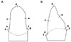
The marginal and internal gaps were measured in compliance with Holmes et al.15 A total of 14 points were measured, i.e., from a to g mesiodistally and from 1 to 7 labiolingually, these were broadly divided into the following four categories: (1) marginal gap (MG), a,g,1,7; (2) cervical gap (CG), b,f,2,6; (3) axial wall at internal gap (AG), c,e,3,5; and (4) incisal edge at internal gap (IG), d,4 (Fig. 2).
To measure the marginal and internal gaps, a silicone replica technique was used. For this, the fabricated metalceramic crown copings were first filled with yellow lightbody silicone (Aquasil Ultra XLV; Dentsply Caulk, Milford, DE, USA), and then placed on a stone die and fitted by applying an even finger pressure of 50 N on an electronic scale. Next, the metal copings were carefully separated, with the hardened yellow light-body silicone film produced used to represent the gaps between the copings and the die. To keep bubbles from rising around the margin of the replicated silicone, and to measure the gap with ease, a contrasting blue light-body silicone (Aquasil Ultra LV; Dentsply Caulk, Milford, DE, USA) was then added. As the light-body silicone film adhering to the stone die was often too thin to resist tearing or to maintain its shape, it was additionally covered with a strong heavy-body silicone for stabilization (Aquasil Ultra Monophase; Dentsply Caulk, Milford, DE, USA). Finally, the replicated silicone was cut using a razor blade along the mesiodistal and labiolingual directions, with the thickness of each section examined under a digital microscope at 160× magnification (KH-7700; Hirox, Tokyo, Japan). Digital images were taken with the digital microscope. The images were measured by the internal stored imaging data software (KH-7700 software Ver. 2.10c; Hirox, Tokyo, Japan) which was equipped to the digital microscope machine (Fig. 3).
The mean gap and standard deviation at each point were compared among the three fabrication methods (casting, computer-aided milling, and DMLS) using a one-way analysis of variance (ANOVA).
A repeated measures analysis of variance (ANOVA) was the used to evaluate any difference between the three fabrication methods with the Greenhouse-Geisser correction method. A type-one error rate of 0.05 was applied in all statistical testing and the statistical software package SPSS Ver. 12.0 (SPSS Inc., Chicago, IL, USA) was used.
RESULTS
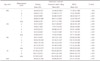
Of the three methods used, the overall mean gap (standard deviation, SD) was lowest for the coping fabricated by the casting method at 58.3 (31.3) µm. This was followed in turn by the computer-aided milling and DMLS methods at 88.9 (39.4) µm, and 103.3 (43.0) µm, respectively, demonstrating a significant difference in the values recorded. Moreover, the cast copings demonstrated the smallest gap at all four of the position categories (MG, CG, AG and IG), whereas those copings made by the computer-aided milling method had a smaller gap than those produced by the DMLS method at CG, AG and IG. However, there was no significant difference observed between the computer-aided milling and DMLS group in the case of the MG (Table 2).
Table 3 shows analysis results comparing the gaps at four different categories. Note that the MG (SD) is the smallest at 57.0 (2.0) µm, with the CG and AG (SD) following in order as 67.8 (1.7) µm and 87.0 (2.2) µm. The largest gap (SD) of 160.5 (4.9) µm was observed at the IG location. Statistically significant differences were found between the categories (P<.001).
DISCUSSION
With the advent of automated systems such as computeraided-design/computer-aided-manufacturing (CAD/CAM), the dental industry has witnessed a series of innovative developments. Compared with conventional casting methods to fabricate dental restorations, these automated methods skip such steps as wax-up, investing, and burn-out, thus simplifying the fabrication in favor of reduced material consumption and greater time efficiency.16 Nonetheless, the marginal and internal fits of dental restorations fabricated with such automated systems are subjected to the effects of multiple factors, including the precision of the scanner used to digitize a working model, the 3D design via computer software, and the precision of the machine used to fabricate the 3D design.17
Meanwhile, the 3D design data relevant to the completed design was saved as an STL file. It should be noted here that STL (stereolithography) files were originally developed by 3D Systems Inc. as a default file format for stereolithography CAD software, and is well known as a "standard tessellation language." As this file format describes the surface structure of a solid 3D model, it is supported by most 3D software products.
The present study compares a conventional casting method to the latest in automated fabrication systems, i.e., the computer-aided milling and DMLS, for the fabrication of copings, using the marginal and internal fit of the resulting structures as the measure of difference.
The findings of this study, however, disagree with those of previous studies. For instance, Örtorp et al.18 used a stereomicroscope and digital photos to investigate the marginal and internal gaps of Co-Cr three-unit bridges for posterior teeth. Their comparison of the fits of dental prosthesis found that a DMLS led to a narrower gap than with casting, whereas a computer-aided milling produced the widest gap of all. In contrast, Quante et al.19 used a silicone replica technique to examine the marginal and internal gaps of Co-Cr single copings for posterior teeth under a microscope. Through this, they found that the mean marginal gap of a dental prosthesis fabricated by a DMLS at two points was 73 and 76 µm, whereas the internal gap on the occlusal surface was in the range of 252-284 µm. Neither of these findings is consistent with the fact that the gap was observed in this study to increase in the order of casting, computer-aided milling, and then DMLS.
To measure the marginal and internal gap between the prosthesis and abutment teeth, a method of cutting and observation incorporating a silicone replica technique, a visual examination using an explorer and a micro CT measurement were suggested.20,21,22,23 This method of cutting and observation is suggested as the most accurate approach to enable the direct validation of sections, yet requires that the specimens be broken. This therefore makes it quite hard to measure multiple points, thus requiring many duplicate specimens for extensive measurements. In contrast, the silicone replica technique is a non-destructive measurement method, which provides a reliable measure of fit than other methods.21,24 It was therefore selected for use in this study so as to allow repeated measurements at multiple points.
The marginal and internal accuracy of prosthetic components is important aspect in their longevity. With regards to the marginal gap of dental prosthesis, the ADA specifications25 define the 'clinical acceptance of bonded prosthesis' as being less than 25 µm. In practice, however, such gaps are often quite difficult to obtain. According to Assif et al., the mean marginal gap is closer to 140 µm, while Hung et al. suggested a value of 50-75 µm.26,27 Gulker even went so far as to suggest that up to 200 µm should be tolerated.28 Meanwhile, Quante et al.19 and Ucar et al.12 reported 76-93 µm and 62.6 (21.6) µm as the marginal gaps of laser sintering-based fabricated copings, respectively. In short, the clinical acceptance of marginal gaps varies quite across different studies. However, despite this, many previous studies have simply applied the 120 µm marginal gap suggested by McLean and von Fraunhofer as the definition of the range of clinical acceptance.29 In this study, the means of MG were 36.96 (9.23) µm, 63.21 (17.89) µm, and 70.98 (18.99) µm in the order of casting, computer-aided milling, and DMLS, while the means of CG were 45.66 (8.97) µm, 70.05 (18.96) µm, and 87.71 (13.08) µm in the order of casting, computer-aided milling, and DMLS. Moreover, the measurements at CG revealed a wider gap in all groups than that of MG. This finding is likely attributable to the curvature of the abutment teeth from the margin to the interior area; nevertheless, the mean gaps at MG and CG were all less than 100 µm. Taken together, the marginal gaps measured in all experimental groups were below the standard clinical acceptance of 120 µm.
The measurement reference for the internal gap of a dental prosthesis is defined differently across studies. Holmes et al.15 defined this internal gap as the vertical distance from the axial surface of the abutment tooth to the internal surface of restorations; however, any clinical acceptance of the internal gaps of fixed dental prosthesis has not been defined so far.12 The internal gaps of single copings fabricated with laser sintering by Quante et al.19 and Ucar et al.12 were, on average, within the range of 252-284 µm and 63 µm, respectively. In the present study, the mean values at AG were 57.44 (12.67) µm, 95.12 (16.52) µm and 108.58 (20.53) µm in the order of casting, computer-aided milling, and DMLS, whereas the means at IG were 127.85 (9.50) µm, 165.23 (32.44) µm, and 188.32 (34.54) µm in the order of casting, computer-aided milling, and DMLS. These findings suggest that precision technology needs to be further improved in order to attain narrower internal gaps in restorations, especially in the case of DMLS.
The gap between the copings and abutment teeth in this study generally tended to increase from the marginal towards the internal surface, with the gap being the widest at IG. Although this finding is comparable to previous studies,18 the gaps observed in this instance were relatively narrower, thus indicating a better fit across all groups. Wide gaps at internal points may cause copings to fracture when completed restorations are bonded in the mouth without proper intervention of cements. Factors in automated fabrication that can influence the fit include the input of information and the accuracy of its processing. Errors arising from such processes are likely to cause the aforementioned increase in the internal gap.
To ensure the accuracy of the experimental results, an in-vitro study was conducted under standardized conditions. Furthermore, the findings are significant in the sense that it establishes the different gaps and clinical applicability of Co-Cr alloy copings fabricated by novel methods.
CONCLUSION
The marginal gaps of all the Co-Cr alloy single copings for metal-ceramic crowns fabricated in this study by automated computer-aided milling and DMLS were found to be within the range of clinical acceptance (<120 µm). Nonetheless, the present findings are still far from definitely demonstrating the superiority of automated system over conventional casting with regards to fitting gaps; and thus further improvement of automated computer-aided milling and DMLS systems is warranted.


 XML Download