

 PDF
PDF ePub
ePub Citation
 Print
Print


INTRODUCTION
Successful restorative treatment with implants is related to the mechanical stability between the abutment and the implant.1 One of the main problems that jeopardizes this stability is screw loosening, the main causes of which include excessive abutment-implant (AI) joint bending and settling effects.2 A retrospective multicenter study showed that loosening of abutment screws occurred in 9.6% of cases over a period of 8 years at 5 private clinics.3 In a recent systematic review, the incidence of screw loosening was 2.7% in external connection implants and 2.4% in internal connection implants.4
Screw preload is the critical mechanical factor that inhibits screw loosening. The preload depends mainly on the tightening torque and also on the design of the abutment screw head and thread, the screw material and lubrication, and the design of the AI connection.2 Clinically, the abutment screw is constantly subjected to extrinsic joint separating forces, such as lateral excursive contacts, cantilevered occlusal contacts, tight interproximal contacts, nonpassive fit of the restoration, and parafunctional habits.2 The joint becomes unstable when external forces exceed the screw joint preload.5 Bickford described the development of screw loosening in two stages. Continuous functional loading initially causes slippage between the threads, releasing the tension of the screw and resulting in a decreased preload. Subsequently, the preload falls below a demanding value and therefore external forces cause the screw threads to turn, preventing its function.6
Previous studies78 have demonstrated that the torque used to tighten the screw is greater than the torque needed to remove the screw. To achieve increased preload levels, it has been recommended to tighten the abutment screws over their suggested torque value to be within 65% of the screw's fracture strength.9
Cyclic loading is desired to simulate masticatory function to test the stability of the screw joint. The irregularities generated during manufacturing may be minimized by mechanical cycling, which causes settling, galling, and sometimes desirable adhesive wear between the two mating surfaces of abutment screw and implant.78101112131415
The design of the AI connection affects screw joint stability.16 Some studies showed that the mechanical stability was higher in internal connection than in external connection systems.1718 However, Tsuge and Hagiwara7 demonstrated that there was no significant difference between external hex (EH) and internal hex (IH) implants with respect to their effects on the loosening of the abutment screw. Nevertheless, Shin et al.16 and Kim et al.19 reported that EH implants were more advantageous than IH implants with regard to torque maintenance after cyclic loading.
Generally, the abutment screw consists of a flat head seat, long stem length, and 6 threads.20 Sopwith21 reported that the numbers of engaged threads were not very significant because most of the loads were carried by the first 3 to 4 threads. Furthermore, a minimum number of threads could reduce friction. The number of threads of the abutment screws in commercially available implant systems varies from 6 to 12.5 in EH implants and is usually shorter than 7.5 in IH implants.
Recently, Kim et al.22 reported that short screws over 3.5 threads had enough fracture strength to protect the integrity of the AI joint in EH implants. Another study found that there were no significant differences in RTVs after repeated tightening and loosening with respect to the abutment screw length.23 Yeo et al.24 also showed that short abutment screws over 3.5 threads could be used to sustain joint stability in EH implants after 2000 thermocycles between 4 and 60℃.
To prevent time consumption and hand fatigue during tightening with longer abutment screws, the joint stability of EH and IH implants with short abutment screws should be studied. No studies were found in the literature that evaluated the AI joint stability in implant-supported single crowns with short abutment screws. The purpose of this study was to evaluate the effects of abutment screw length and cyclic loading on the removal torque values (RTVs) in EH and IH implants. The null hypothesis was that there was no difference in RTVs of EH and IH implants with various abutment screw lengths between before and after cyclic loading.
MATERIALS AND METHODS
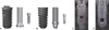
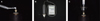
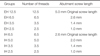
Twenty EH (USII, Osstem, Seoul, Korea) and 20 IH implants (TSIII, Osstem, Seoul, Korea) were used. Abutments for screw-retained single crowns (UCLA temporary abutment, Osstem Seoul, Korea) were connected to each implant (Table 1, Fig. 1). The abutment screws were classified into 8 groups according to the length and the number of threads. To prepare different abutment screw lengths, the screws were cut with aluminum oxide cutting discs (Se-Jong) and polished with a gold polishing kit (Shofu Inc., Kyoto, Japan) (Fig. 2A, Table 2).
Abutment crowns were fabricated by self-curing acrylic resin (Tokuso Curefast, Tokuyama Dental, Tokyo, Japan) to resemble the maxillary right first molar of a dentoform. Screw-retained crowns were constructed with a bucco-lingual width of 9 mm and a mesio-distal width of 9.5 mm. To fabricate implant-supported single crowns with the same width and shape, a template of the dentoform tooth was duplicated with vinyl polysiloxane (Exafine Putty Type, GC Corp, Tokyo, Japan). The implant specimens were positioned vertically in 2.5 × 2.5 × 2.1 cm resin blocks (Orthoplast, Vertex Dental, Zeist, Netherlands) (Fig. 2B).
The abutments were fastened to the implants, while the resin blocks were fixed to the jig. Then, 20 Ncm of recommended insertion torque was applied to each abutment screw using a hand torque wrench (Biomet 3i).25 Ten minutes later, the same tightening torque was applied again to compensate for embedment relaxation (Fig. 3A).26 After 5 minutes, the initial RTV was measured with a digital torque gauge (MGT12, MARK-10 Co., New York, NY, USA) (Fig. 3B and Fig. 3C). Subsequently, to prepare the implant assembly for the loading test, the abutment screws were tightened with 20 Ncm torque twice with 10-minute intervals. The access holes were filled with gutta percha and composite resin (Filtek Z250, 3M ESPE, St. Paul, MN, USA).25
Customized jigs were constructed to apply load parallel to the implant long axis at the central fossa of the maxillary right first molar (Fig. 4). The bottom of the specimen was fixed to the jig, which was installed in a cyclic loading machine (WON CLMC-04-1, WON Engineering, Iksan, Korea). Flat surfaces were prepared for loading at the center of the access hole, which was lubricated with thin layers of grease to reduce friction. The implant assemblies were loaded with 50 N at a 1-Hz frequency for 16,000 cycles, which corresponded to approximately 3 weeks of normal masticatory function.27 After cyclic loading, the post-loading RTVs were measured with a digital torque gauge, as described in the measurement of initial RTVs.
Selected specimens were examined using a scanning electron microscope (SEM, JEOL, JSM-6360, Tokyo, Japan) to detect possible microdamage on the screw surface. Examinations of the screw threads before and after loading at ×200 magnification were analyzed.
One-way analysis of variance (ANOVA) and Tukey's (HSD) tests were performed for analysis of initial and post-loading RTVs among the 8 groups. The paired t-test was performed to compare initial RTVs with post-loading RTVs in each group. P < .05 was considered to represent a statistically significant difference.
RESULTS
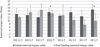
The RTVs' means, standard deviations (SD), % torque maintenance (%TM) and the difference between the initial and post-loading RTVs are shown in Table 3. The mean values of both the initial and the post-loading RTVs were lower than the insertion torque in all groups (Table 3, Fig. 5). The paired t-test revealed that the post-loading RTVs were significantly lower than the initial RTVs in the EH 2.5 and IH 2.5 groups (P < .05). One-way ANOVA and Tukey's HSD test did not reveal statistically significant differences in the initial RTVs among the 8 groups, whereas the post-loading RTVs of the EH 6.5 and EH 3.5 groups were higher than those of the IH 3.5 group (P < .05).
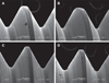
The SEM images showed rough spots, grooves, and irregularities on the surface of the new abutment screws. Structural changes, such as linear scratches, rounding of the thread crests, and mild burnishing on the thread flanks, were observed on the abutment screws after loading.15 However, abnormal wear or damage caused by cyclic loading was not observed on abutment screws in all of the groups (Fig. 6).
DISCUSSION
The null hypothesis of this study was rejected based on the significant differences in RTVs for before and after loading among the various abutment screw groups. RTV is a measure of the remaining preload in the abutment screw.10 Abutment screw length and cyclic loading affected RTVs in EH and IH implants. The mean initial RTVs were lower than the insertion torque of 20 Ncm in all groups, ranging from 12.17 to 16.89 Ncm in this study. The %TM of the initial RTV was approximately 61 to 84%. The reduced RTVs in comparison to the tightening torque resulted from embedment relaxation.9 When the abutment screw is subjected to external loads, micromovement occurs between the screw and the internal thread of the implant. The fine irregularities and microroughness on the screw surface, shown in SEM examination (Fig. 6A and Fig. 6C), were smoothened and flattened. Wear of the contact areas brings the two metallic surfaces closer to each other.61026 It has been reported that 2 to 10% of the initial preload is lost as a result of settling.7911 Tsuge and Hagiwara7 compared the initial RTVs of the titanium (Ti) alloy abutment screw tightened with 20 Ncm insertion torque in EH and IH implants (Osseotite, Biomet 3i), yielding 18.9 Ncm (94.5%) and 18.3 Ncm (91.5%), respectively.
In contrast to their study, %TM in other studies was usually lower than 90%. Haack et al.28 measured RTVs in UCLA abutment/EH implant assemblies (Implant Innovations), yielding values of 74.6% in the gold alloy screw and 74.2% in Ti alloy screw after tightening with 32 Ncm of insertion torque. Khraisat et al.10 also reported that the initial RTV decreased to 77% (24.5 Ncm) of the insertion torque in CeraOne abutment/Brånemark MK IV implant assemblies (Nobel Biocare). Delben et al.8 also reported that the initial RTVs in EH implants (Biomet 3i) decreased to 68% (23.9 Ncm) of the insertion torque (35 Ncm) in prefabricated gold UCLA abutments and to 66% (23.3 Ncm) in cast Ti UCLA abutments. The initial RTVs in this study were comparable with the results of Delben et al.; our results were 14.11 Ncm (70%) and 13.04 Ncm (65 %) in the EH 12.5 and IH 6.5 groups, respectively, with the original screw length after tightening with a 20-Ncm insertion torque.
The abutment screw threads differ among implant systems. The thread number of the original screws used in this study was 12.5 for EH implants (USII, Ossetem), the same as in the Biomet 3i implant systems; it is 7.5 for the Warantec implant system and 6 for the Nobel Biocare system. In the original design of Brånemark implants, the abutment screw had 6 threads to reduce the friction and the long stem length for the elongation.20
The length of the abutment screw did not show any significant differences in RTVs before and after cyclic loading, except for the EH 2.5 and IH 2.5 groups. These findings were in accordance with the those of Sopwith21 and Choi et al.,23 who confirmed that 3 to 4 threads in screw were adequate to maintain the integrity of the AI joint. Yeo et al.24 also demonstrated that thermal cycling had no significant effect on the RTVs of 7 groups with different abutment screw lengths in EH implants (Warantec). RTVs before and after thermal cycling ranged from 23.0 Ncm (77%) to 25.5 Ncm (85%) in the EH 3.5, 6.5, and 9.5 groups after tightening with 30-Ncm torque. The mean initial and postloading RTVs in the EH 3.5, 6.5, 12.5 groups were between 12.06 Ncm (60%) and 16.74 Ncm (84%).
The initial and post-loading RTVs in the EH 12.5 group were 14.11 and 12.06 Ncm, respectively, and the values showed no significant difference in this study. These findings were in accordance with those of Delben et al.,8 who demonstrated that the mechanical loading with 1 × 10⁶ cycles of 50 N had no significant effect on RTV differences in 4 of the 5 groups. However, they reported that the cast Ti abutment with a resin veneer showed significantly higher RTV after cyclic loading. Tsuge and Hagiwara7 also reported that the post-loading RTVs were significantly increased relative to the initial RTVs in both implant systems, even though the initial RTV was approximately 10% lower than the insertion torque. They explained the increase in RTV was due to the improved fit from desirable adhesive wear between the thread of the Ti abutment screw and the internal thread of the implants after lateral cyclic loading. However, they concluded that the difference in the two AI connection systems had no effect on the difference of RTVs before and after loading, but the difference in two screw materials did. This may explain the increased post-loading RTVs in correlation to the initial RTVs for the EH 6.5, EH 3.5, and IH 6.5 groups in this study.
Nonetheless, Cibirka et al.1 stated that in Procera machined abutment/EH implants (Nobel Biocare), the RTV of the gold alloy screw tightened with 32 Ncm decreased to 14.40 Ncm after dynamic loading of 20 to 200 N for 5 × 10⁶ cycles. Khraisat et al.14 also found that 1 × 10⁶ cycles of lateral cyclic loading with 0 to 50 N at 1.25 Hz significantly lowered the RTV in CeraOne abutment/EH implants (Nobel Biocare) compared to a 0.5 × 10⁶ loading cycle. Khraisat et al.14 concluded that long-term loading significantly affected the RTVs under a centric lateral load. Additionally, Al Jabbari et al.15 recommended applying torque to the abutment screws again after the first 6 months of service, followed by annual reapplication of torque.
The screw material, shape, size, and coating material are crucial to maintaining preload and the stability of the AI connection.18 In IH implants, the joint stability of the implant-supported single crown is achieved from the clamping force of the abutment screw and the frictional force developed by contact between the conical mating metallic surfaces of the AI connection.29 However, the IH 3.5 group exhibited significantly lower post-loading RTV in comparison with those of EH 6.5 and EH 3.5 groups in this study.
There are three studies that examined the RTVs of GSII implants, the predecessor of TSIII implants used in this study. Kim and Shin30 compared the initial and post-loading RTVs of 18.12 Ncm (60%) and 17.67 Ncm (59%), respectively, and reported no significant differences. Shin et al.16 also compared the initial and post-loading RTVs in IH and EH implants using tungsten carbide/carbon-coated titanium (WC/C Ti) alloy abutment screws in both systems. The insertion torque, initial RTV, and post-loading RTV after 1 × 10⁵ cycles of 5-mm off-axis loading with a 10 to 150 N load at 10 Hz were 30, 26.0, and 24.6 Ncm in USII implants, and 30, 24.8, and 12.5 Ncm in GSII implants, respectively. They confirmed that IH implants had a weaker AI connection than EH implants.
Kim et al.19 reported that two-piece abutments in GSII implants exhibited 2.4 µm of settling after mechanical loading with 1 × 10⁵ cycles at 14-Hz under 250 N. The post-loading RTV (16.92 Ncm) was significantly lower than the initial RTV (20.5 Ncm), whereas two-piece abutments in USII implants showed 0.6 µm of settling and no difference in RTVs before and after cyclic loading. They explained that the elongated abutment screw was shortened with the settling of the abutment in GSII implants after loading, which could result in a significant decrease in the post-loading RTV. However, the abutment screws in GSII implants consisted of WC/C Ti alloy, while those in USII were Ti alloy.
The post-loading RTVs ranged from 7.47 to 16.74 Ncm in all groups. The differences in RTV before and after loading ranged from 0.77 to - 4.56 Ncm in EH implants and from 6.98 to - 0.37 Ncm in IH implants. There was no significant difference in the RTVs within the IH 6.5 group before and after loading in this study. However, the post-loading RTV of the IH 3.5 group was 7.47 Ncm, and it showed 37%TM. The decrease in post-loading RTVs tended to be greater in IH relative to EH implants, and these results were in agreement with those of previous studies.1619
Even with the reduction of RTV, no group exhibited abutment screw loosening after loading. This might imply that the remaining torque maintained screw joint stability for a longer period within the conditions of this study.
The limitation of this study was that the abutments used were not the stock abutments. Temporary abutments were inevitably selected in both AI connection systems due to the differences in screw materials: Ti alloy for USII implants and WC/C Ti alloy for TSIII implants. The short period of cyclic loading was applied to test the temporary restorations.24 Future studies should consider applying a lengthened period of cyclic loading in stock abutments with various lengths of abutment screws.
CONCLUSION
Both the mean initial and the post-loading RTVs were lower than the insertion torque in all groups. The post-loading RTVs were significantly lower than the initial RTVs in the EH 2.5 thread and IH 2.5 thread groups (P < .05). The initial RTVs exhibited no significant differences among all 8 groups, whereas the post-loading RTVs of the EH 6.5 and EH 3.5 groups were higher than those of the IH 3.5 groups (P < .05).
Within the limitations of this study, abutment screws with a minimum of 3.5 threads showed no significant difference in RTVs in IH and EH implants after cyclic loading. The EH implants with over 3.5 threads were much more advantageous than the IH implants with regard to torque maintenance after cyclic loading. In the case of EH implants, shortening of the abutment screw length would be recommended for the preservation of preload and ease of manipulation.


 XML Download