

 PDF
PDF ePub
ePub Citation
 Print
Print


INTRODUCTION
Precise positioning of the bracket is paramount to achieve the full potential of the straight-wire appliance and improve the treatment results and reduce the treatment time.1,2 Although the indirect bonding (IDB) method enables precise placement of the brackets on the tooth surface, thereby reducing the chair time,3-9 it has a few disadvantages-cumbersome manual procedure, high cost, technique- and material-sensitivity, and significant learning curve.8,10,11
Keim et al.10 and Sheridan8 reported that 10% to 12% of the orthodontists in the United States have used the IDB method. However, several studies have been undertaken to overcome the drawbacks of the conventional IDB technique, such as the manner in which the brackets are applied to the plaster casts and the specialized materials and techniques used to fabricate the transfer trays and those required to bond the brackets to the teeth.9,11-16 A survey conducted among orthodontic residents in the United States revealed that 46% of them plan to use IDB in their clinical practice.17
Recent reports on the application of the computer-aided designing and manufacturing (CAD/CAM) technology for establishing a virtual setup and fabricating transfer tray/jigs2,18,19 have greatly improved the IDB process. This case report introduces a new virtual orthodontic treatment system for constructing three-dimensional (3D) virtual models, executing a 3D virtual setup, facilitating the placement of the virtual brackets on the predetermined position, and fabricating the transfer jig with a customized bracket base for IDB using the stereolithographic technique.
DIAGNOSIS AND ETIOLOGY
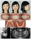
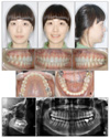
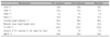
A 26-year-old woman presented with anterior open-bite and crowding in the upper and lower arches, despite having an acceptable profile and balanced facial proportion (Fig 1). Intraoral examination revealed Class I canine and molar relationships and narrow and tapered upper dental arch (Fig 1). Cephalometric analysis indicated a Class I skeletal relationship and dentoalveolar openbite (Fig 1 and Table 1). The extent of upper incisor exposure in relation to the upper lip was within the normal range (3.6 mm, Table 1). History taking and habit evaluation revealed that she did not have a tongue thrusting habit.
TREATMENT OBJECTIVES
To reduce the crowding of the upper and lower arches while maintaining the patient's profile, the non-extraction approach was chosen. Further, to correct the narrow and tapered upper arch form (Fig 1), surgically assisted rapid palatal expansion was recommended, considering the patient's age. However, the patient refused surgery, and therefore, maxillary expansion was performed using a screw (Hyrax, Dentaurum, Germany).
To correct the anterior openbite, intrusion of the upper posterior teeth using orthodontic mini-implants was planned because the patient's upper incisor exposure was normal (Table 1).
TREATMENT PROGRESS
Process of virtual orthodontic treatment system
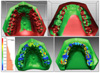
Construction of 3D virtual models
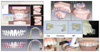
In this case, after 10 days of maxillary expansion using a screw (Hyrax, Dentaurum, Germany), sufficient space for decrowding was obtained. After a 10-week retention period, accurate pretreatment plaster models were obtained by silicone rubber impression with a centric occlusion (CO) wax bite. Then, 3D scanning of the plaster models was performed using a 3D scanner (noncontact laser scanner, Orapix, Seoul, Korea; accuracy, ± 20µm). The acquired scan data were edited to obtain a pretreatment 3D virtual model using 3Txer program (Orapix, Seoul, Korea; Fig 2A).
Execution of the 3D virtual set-up and positioning of virtual brackets
The acquired arch form was compared with the commercially available preformed archwires by using the 3Txer program (Orapix, Seoul, Korea). The arch form most similar to that acquired was the Damon arch form (Ormco, Sybron Dental Specialties, Orange, CA, USA). By adjusting the arch form and width and relocating the individual tooth into Class I canine and molar relationship, on the basis of Andrews' 6 Keys to normal occlusion (Fig 2A),20 a 3D virtual setup was constructed. Then, the prescribed virtual brackets were placed on the facial axis (FA) point with virtual 0.021 × 0.025 stainless steel wires (Fig 2A).
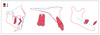
Positioning of the virtual transfer jig and fabrication of the real transfer jig using the stereolithographic technique
To ensure the accuracy of the customized bracket base, we checked for interference between the bracket base and the tooth surface. Then, the virtual transfer jig for each tooth was placed using a software program (3Txer, Orapix, Seoul, Korea, Fig 2B). The transfer jig consisted of a customized occlusal cap and a bracket-mounted connector.
The real transfer jig was fabricated using a stereolithographic rapid-prototyping machine (Viper 2, 3D systems, Circle Rock Hill, SC, USA) (Fig 2B). Accurate seating of the real transfer jig on the individual tooth was crucial for the next step.
Fabrication of the customized bracket base
In the dental laboratory, the prescribed real brackets were combined with the real transfer jig. Adhesive paste (Transbond XT, 3M Dental Products, St Paul, MN, USA) was applied to the bracket base, and the bracket-real transfer jig complex was fitted over the pretreatment plaster models and was slightly cured to prepare customized bracket bases (Fig 2B).
Procedure for IDB
The degree of adaptation of the bracket-real transfer jig complex to the individual tooth was assessed. After etching the enamel surfaces with 37% phosphoric acid gel (3M Dental Products, St Paul, MN, USA) for 30 seconds, a primer (Transbond XT, 3M Dental Products, St Paul, MN, USA) was applied to the etched tooth surface in a thin film. During this procedure, care was taken to prevent saliva contamination and ensure proper isolation with cheek retractors. A small amount of adhesive paste (Transbond XT, 3M Dental Products, St Paul, MN, USA) was applied to the customized bracket bases. Then, the bracket-real transfer jig complex was mounted on the individual tooth and was slightly cured by applying finger pressure onto the tooth surfaces. After curing, the real transfer jig could be removed (Fig 2B).
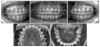
After 10 days of maxillary expansion using a screw (Hyrax, Dentarum, Germany), sufficient space for decrowding was obtained. After a 10-week retention period, IDB was performed according to the protocol described above. An interval of 7 months was allowed for the leveling/alignment of the dentition and intrusion of the upper molars by using an elastomeric chain and orthodontic mini-implants in the buccal-attached gingival between the midpalatal area and the upper second premolar and between the midpalatal area and the first molar (length, 8 mm and 6 mm; diameter, 1.6 mm 1.6 mm, respectively; Jeil Med. Co. Seoul, Korea). At the end of this period, normal overbite and overjet were obtained (Fig 3). After 13 months of treatment, fixed lingual retainers were bonded on both the upper and lower anterior segments. A circumferential retainer was added to ensure stability in the upper arch.
RESULTS
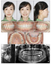
There was no significant change in the patient's facial profile even after the decrowding of the upper and lower anteriors. Class I canine and molar relationships were well maintained (Fig 4). Because of the intrusion of the upper molars and uprighting of the upper and lower incisors, the anterior openbite was corrected to normal overbite (Fig 5). However, to prevent the compensatory extrusion of the lower molars during the intrusion of the upper posterior teeth, it was necessary to simultaneously apply the intrusive mechanics to the lower molars by using a lingual arch and orthodontic mini-implants. The change in the anterior overbite is essential during the intrusion of the molars. In addition, excessive use of the vertical elastics in the anterior teeth should be avoided to prevent a relapse of the anterior openbite.
Superimposition of pre- and post-treatment 3D virtual models showed that the upper and lower arches were moderately expanded, especially in the canine and premolar regions (Fig 6). Superimposition of the 3D virtual setup models and the post-treatment 3D virtual models showed that the final outcome was only slightly different from that predicted (Fig 6). The patient's profile and occlusion were well maintained after 6 months of retention (Fig 7).
DISCUSSION
Sachdeva21 suggested that computer-aided 3D technology can provide 3D tools for diagnosis, monitoring, and patient communication as well as facilitate precise bracket bonding for customized orthodontic treatment. Garino and Garino22 reported that computer-aided IDB enables accurate placement of the brackets, while Ciuffolo et al.19 applied computer-aided technology to develop a rapid prototyping procedure to facilitate the designing and production of individualized trays. If a virtual orthodontic treatment system can be developed, then each step of the treatment process, including the construction of a 3D virtual model, establishment of a 3D virtual setup, positioning of the virtual brackets and virtual transfer jig, fabrication of the real transfer jig using a stereolithographic technique, fabrication of the customized bracket base, and execution of the IDB procedure, can be performed without significant errors.
Cho et al. recommended that a 3D virtual setup should aim at overcorrection for rotation up to 5 degree and tooth movement of 0.5 - 1.0 mm.23 When checking the occlusion, the contact between the functional cusp and central fossa/marginal ridge should be balanced throughout the dentition. During virtual bracket positioning, the facial axis points on the labial and buccal surfaces should be lined up under consideration of the curve of Spee.
Since the stability of the real transfer jig is paramount to successfully fabricating a customized bracket base and executing IDB, the occlusal coverage of the virtual transfer jig should be extended to the mesial and distal marginal ridges and the labial/buccal and lingual line angles of each tooth crown. If there is interference between the bracket base and tooth surface, the bracket position should be changed or the colliding area of the bracket base should be marked for future grinding-out. Further, proper rigidity of the customized occlusal cap and bracket-mounted connector in real transfer jig should be ensured.
The dental laboratory technician should exercise caution when preparing the bracket-real transfer jig complex and should apply an adequate amount of adhesive paste (Transbond XT, 3M Dental Products, St Paul, MN, USA) under the bracket base. During the light curing of the customized bracket base on the pre-treatment plaster models, care should be taken to avoid excessive finger pressure on the bracket-real transfer jig complex.
Before IDB, the fitness of the customized bracket base and the stability of bracket-real transfer jig complex should be checked. The IDB procedure can be initiated from the posterior teeth and extended to the anterior teeth or vice versa. The crowded area should be bonded separately, or the procedure should be delayed until decrowding is completed.
Compared to the traditional method of manual set-up and fabrication of transfer jig, this new virtual orthodontic treatment system can optimize bracket positioning, reduce excessive laboratory burden, and provide several treatment-planning options. In addition, it can greatly facilitate the communication between the doctor, dental laboratory technician, and the patient.
CONCLUSION
The virtual orthodontic treatment system produced an acceptable treatment result in this case of mild crowding treated without extraction; additional cases should be treated using this system, and the post-treatment results should be compared with the 3D virtual setup models to obtain feedback. This will greatly support doctors and dental laboratory technicians during the learning curve.
 XML Download