

 PDF
PDF ePub
ePub Citation
 Print
Print


The ideal goal of radiofrequency (RF) ablation is the ablation of a peripheral margin of 0.5-1 cm of normal hepatic tissue surrounding the tumor, as well as the entire tumor itself (1-5). In general, a single ablation, or two, may be adequate for tumors less than 3 cm in diameter where an electrode at least 3 cm in diameter is used.
For treating larger tumors, multiple overlapping ablations are imperative, according to tumor size and shape (1-5). In a recent study using a computer-generated three-dimensional model, various composite thermal zones were created by overlapping multiple ablation spheres (6). However, when ultrasound guidance is used, the creation of overlapping ablations in large tumors may in practice be difficult. The ablation procedure almost always creates numerous microbubbles in heated tissue, and these increase the echogenicity of the ablated area at ultrasound scanning (7, 8). A transient hyperechoic zone may obscure unablated portions, and further placement of the electrode at the target site may thus be difficult or impossible.
A recently developed coaxial electrode system (LeVeen CoAccess Electrode System, RadioTherapeutics Corporation, Mountain View, Cal., U.S.A.) may help overcome this problem. The system consists of a LeVeen CoAccess electrode and introducer set, and after placing the multiple cannulae (of introducers) at appropriate sites within the tumor, for the purpose of performing multiple overlapping ablations, a large tumor can be sequentially ablated. Using ultrasound guidance, this technique can be successfully performed regardless of the existence of a transient hyperechoic zone. Few experimental studies involving a real ablation zone have, however, been performed using this technique (9).
The purpose of this study was to determine the sizes and configurations of the thermal zones created by overlapping ablations using a coaxial RF electrode and multiple cannulae in ex-vivo bovine liver.
MATERIALS AND METHODS
RF System
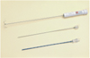
We used a coaxial electrode system (RadioTherapeutics Corporation) consisting of a 16-gauge LeVeen CoAccess electrode and introducer set, the latter comprising a stylet and a cannula (Fig. 1). The CoAccess electrode is equipped with an uninsulated 16-gauge outer electrode that houses ten solid, retractable, curved hooks. When these are fully extended, their diameter is 3.5 cm and the device assumes an umbrella shape. The 15-gauge insulated cannula guides placement of the electrode, and can provide access to the target tissue. A 200-W monopolar RF generator (RF 3000; RadioTherapeutics Corporation) is used as the energy source, and four ground pads under a copper plate are also employed. For ablation, the tip of the RF electrode is advanced towards the target tissue, and the curved electrodes are fully deployed. Power output is initially set at 50 W, and every 60 sec a 10 W increase is applied until 110 W is attained. The device is maintained at peak power for 15 mins or until it impedes out (a rapid rise in impedance stops current flow and ablation). If this occurs, it is turned off for 30 sec and then restarted at 70% of the maximum power attained at the time of impeding out. Application continues until the generator once again impedes out, or for 15 mins. If the device does not impede out during the first cycle, it is switched off for 30 secs and then restarted at maximum power and run until it impedes out or 15 mins have elapsed. The algorithm is based upon tissue impedance rather than tissue temperature (1).
RF Ablation
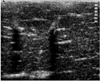
Twenty-four ablation zones, of five different kinds, were induced in seven explanted, fresh bovine livers placed on the copper plate with the ground pads at room temperature (about 20℃). Ten single-ablation zones were created. Also, 14 composite zones with two, four, and six ablation spheres were created using an overlapping technique. Assisted by real-time ultrasound guidance, we used introducer sets to insert multiple cannulae at least 3 cm inside the liver prior to RF ablation (Fig. 2). For ultrasound, a 12-5 MHz linear transducer (HDI 5000; Advanced Technology Laboratories, Bothell, Wash., U.S.A.) was used. We aimed to maximize the size of the composite zones (6). All space within such a composite zone was surrounded by one or more individual spheres, and in total, 56 sessions were performed.
MR Imaging
For immediate postprocedural MR examinations, a 1.5-T MR imager (Horizon, GE Medical System, Milwaukee, Wis., U.S.A.) with a head coil was used, and a T2-weighted fast spin-echo sequence (TR 3084-5200/TE 102-104/ETL 12/NEX3-4/matrix 256×192/FOV 18-20 cm) was employed. Coronal images with a slice thickness of 2-3 mm and no interslice gap were obtained in all thermal zones, and axial images in twelve zones. Source and multiplanar reformatted images were archived with a picture archiving and communication system (PACS, PathSpeed Workstation; GE Medical Systems).
Within 60 minutes of RF ablation and 30 minutes of MR imaging, specimens of single- and double-ablation zones were cut into 1-cm-thick slices along the electrode axis, and macroscopically evaluated by measuring with calipers the two longest dimensions, one along the electrode axis and the other perpendicular to it. Specimens of four- and six-ablation zones were cut perpendicular to the electrode axis, and their longest dimensions were measured. On the basis of previous reports (10-12), we used the junction between the red and pink rims seen at gross pathologic examination to define the outer margin of definite cell death.
At MR imaging, the dimensions of low-signal zones were measured; peripheral marginal zones were not included. The dimensions of the ablation zones were based on the consensual findings of three radiologists, while their volumes were determined at maximal magnification on a PACS monitor by one radiologist using an area-measuring tool and summation-of-areas technique (13). For three-dimensional reconstruction of MR images, a volume-rendering technique (V-works 4.0, CyberMed Inc., Seoul, Korea) was used, and the volume and shape of the composite ablation zones was thus accurately determined.
RESULTS
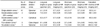
Mean long-axis and short-axis lengths and the calculated volumes of ablation zones are summarized in Table 1. During all ablation sessions, the RF device impeded out before power output reached 110 W.
Single-Ablation Zones
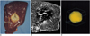
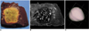
Using real-time ultrasound guidance, the bovine liver became diffusely echogenic in an elliptic fashion. The short axis of the zone followed the course of the electrode, and its long axis lay perpendicular to the probe and along the plane created by the deployed curved distal hooks. Gross pathologic examination showed that the created zone was sharply demarcated into three distinct regions. A central, predominantly pale zone was surrounded by a variably sized red ring, and in eight of ten zones, a pink, variably sized outer rim surrounded the pale zone and red ring, and showed variable demarcation from normal liver (Fig. 3A). The long-axis (transverse) lengths of single-ablation zones ranged from 3.7 to 4.4 cm (mean, 4.1 cm; standard deviation [SD], 0.19 cm), and their short-axis (longitudinal) lengths from 3.6 to 4.4 cm (mean, 4.0 cm; SD, 0.17 cm). T2-weighted MR images demonstrated relatively discrete low-signal thermal zones (Fig. 3B). Multiple curvilinear and spotty regions of hyperintensity probably indicated hemorrhagic products at hook insertion sites. At MR imaging, the long-axis lengths of single-ablation zones ranged from 3.5 to 4.1 cm (mean, 3.7 cm; SD, 0.21 cm), and the short-axis lengths from 3.5 to 4.0 cm (mean, 3.7 cm; SD, 0.18 cm). The volumes of ablation zones ranged from 26.2 to 38.5 cm3 (mean, 33.3 cm3; SD, 4.1 cm3). Each reconstructed three-dimensional image appeared as an irregularly contoured sphere (Fig. 3C).
Double-Ablation Zones
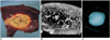
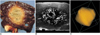
Eight thermal ablation zones (cylinders) with two ablations each were created by overlapping ablation spheres by 23% and 58% of their diameter. Two different kinds of double-ablation zone were designed for the largest composite ablation zone model and cylindrical model, respectively (6). The intervals between electrode tips were 3.2 cm (23% overlap of single-ablation zones 4.1 cm in diameter) and 1.7 cm (58% overlap of single-ablation zones). The gross pathologic findings showed that the long-axis (transverse) lengths of double-ablation zones with 23% overlap ranged from 7.0 to 7.7 cm (mean, 7.3 cm; SD, 0.31 cm), and those with 58% overlap, from 6.0 to 6.4 cm (mean, 6.2 cm; SD, 0.17 cm). The short-axis (longitudinal) lengths of double-ablation zones with 23% overlap ranged from 3.0 to 3.9 cm (mean, 3.5 cm; SD, 0.23 cm) (fissure area), and those with 58% overlap, from 3.8 to 4.6 cm (mean, 4.3 cm; SD, 0.16 cm) (Figs. 4, 5). At MR imaging, the volumes of double-ablation zones with 23% overlap ranged from 60.3 to 76.4 cm3 (mean, 68.1 cm3; SD, 6.6 cm3) and those with 58% overlap, from 52.4 to 68.9 cm3 (mean, 60.2 cm3; SD, 6.8 cm3). Double-ablation zones with 58% overlap were more spherical (elliptical) than those with 23% overlap, and in the latter, fissures were evident (Fig. 4A).
Four-Ablation Zones
Three thermal ablation zones (cakes) with four ablations each were created by rectangularly overlapping ablation spheres by 23% of their diameter. The intervals between electrode tips were 3.2 cm (23% overlap of single-ablation zones 4.1 cm in diameter). On transverse sections of specimens, the long-axis (diagonal) lengths of four-ablation zones ranged from 8.5 to 9.7 cm (mean, 9.1 cm; SD, 0.60 cm), and the lateral measurements from 6.3 to 7.0 cm (mean, 6.7 cm; SD, 0.45 cm). The short-axis (longitudinal) lengths of four-ablation zones ranged from 3.0 to 4.1 cm (mean, 3.7 cm; SD, 0.40 cm) (fissure area) (Fig. 6). The volume of ablation zones seen at MR imaging ranged from 128.4 to 162.1 cm3 (mean, 144.8 cm3; SD, 16.9 cm3).
Six-Ablation Zones
Six-ablation (six-sphere) zones were designed with four spheres in the x-y plane and two along the z-axis. By accurately placing electrodes (cannulae) by means of ultrasound guidance, we produced the largest composite zones (spheres), with 23% overlap of single-ablation zones 4.1 cm in diameter. Transverse sections of specimens showed that the long-axis (diagonal) lengths of six-ablation zones with 23% overlap ranged from 9.0 to 9.9 cm (mean, 9.4 cm; SD, 0.45 cm), and the short-axis (side) lengths from 6.8 to 7.5 cm (mean, 7.2 cm; SD, 0.34 cm) (Fig. 7). The volume of ablation zones seen at MR imaging ranged from 182.3 to 221.8 cm3 (mean, 202.9 cm3; SD, 19.8 cm3). Each reconstructed three-dimensional image appeared as a composite zone (sphere), with no definite pits at the junction of the three small spheres.
DISCUSSION
Livraghi et al. (14) reported a complete necrosis rate of 90% in 42 patients with 52 small hepatocellular carcinomas (≦3 cm in diameter) after RF ablation. This rate decreased, however, to 71% for medium hepatocellular carcinomas (>3.0-5.0 cm) and to 25% for large ones (> 5.0 cm). Thus, for the complete treatment of larger tumors, multiple overlapping ablations must be performed. According to Dodd et al. (3), tumors less than 2 cm in diameter can, in theory, be treated during a single session; those ranging from 2 to 3 cm require six overlapping ablations, and those larger than 3 cm require 12 overlapping ablations.
The challenge posed by the demands of clinical practice is formidable, but the multiplication of treatment positions is a potential limitation. Especially when ultrasound is used for guidance, accurate, multiple placement of an electrode is in fact impossible owing to the presence of a transient hyperechoic zone (with numerous microbubbles) in the treated area following earlier ablation sessions (7, 8). However, ultrasound has still been preferred to CT or MR imaging for guidance during RF ablation (1, 5, 7). A recent study reported that simultaneous RF ablation with dual probes could overcome the difficulty of probe repositioning during overlapping ablations (9).
The results of our study, in which a recently developed coaxial electrode system was used, showed that the problem could be overcome. Using an ultrasonically guided introducer and multiple cannulae previously inserted at precisely determined positions, sequential ablations were performed. According to our results, based on the schema designed by Dodd et al. (6), the RF ablation of hepatic tumors of medium size can be more complete and involve fewes sessions if a coaxial electrode system and an overlap technique are used.
Our study findings also showed that the axis lengths of the ablation zones seen at MR imaging were slightly shorter than those at gross pathologic examination. One of the reasons for this is that the junction between a low-signal area and a peripheral marginal zone was used as the outer margin of the zones at MR imaging. The boundaries of the majority of peripheral marginal zones with slightly low signal were vague.
Dodd et al. (6) also presented two other complex computer models, a 14-sphere model and a cylindrical model with 27 overlapping ablations. However, overlap techniques using a coaxial electrode system in our study cannot be adopted in those models. Because previously inserted cannulae interrupt an ultrasound probe, the use of overlap techniques which depend on a coaxial electrode system in the six-sphere model can present practical difficulties, and this is an inherent flaw.
Our study suffers a further limitation: this ex-vivo procedure cannot be directly adopted for use in a clinical setting. Using the same RF device, the size of the ablation zone in vivo was smaller than when ex vivo (15). Furthermore, the greater in-vivo variation in the size and shape of the ablation zone was caused mainly by the heat-sink effect. Nevertheless, the use of a coaxial RF electrode, as suggested in our study, has potentially broad clinical merit and can assist in the planning of a methodologic strategy.
In summary, using a coaxial RF electrode and multiple cannulae, together with ultrasound guidance and precise overlapping ablation techniques, we successfully created predictable thermal zones in ex-vivo bovine liver.

 XML Download