

 PDF
PDF ePub
ePub Citation
 Print
Print


INTRODUCTION
Primary implant stability is essential for the successful formation of bone tissue at the bone-implant interface. Excessive micromotion (relative displacement between the implant and bone) may cause osseointegration failure between the bone and implant [1]. Therefore, primary stability is one of the prerequisites for immediate loading. The design of the implant, quantity and density of the bone, and placement and surgical technique influence primary stability [234567].
Previous studies have shown a relationship between the displacement/micromotion of implants and the implant macrogeometry [8910], thread design [4], surface roughness [11], abutment angulation [12], bone density [13], cortical bone thickness [14], and loading direction [915]. We also previously examined the effect of bone density and crestal cortical bone thickness on micromotion [16]. However, the effects of the placement technique, such as implant tilting, remain unclear, although distal implants are frequently inclined to support a fixed full-arch prosthesis because of the anatomic limitations of the residual alveolar bone.
The occlusal loading patterns of implants significantly affect the implant stability and peri-implant stress/strain distribution. Peri-implant stress and strain increase as the loading angle increases [17]. However, few scientific studies have examined the effects of the loading angle on the displacement or micromotion of implants [15].
As with other mechanical problems in implant dentistry, finite element analysis (FEA) is an efficient technique for evaluating micromotion [9]. To date, several reports have evaluated the micromotion of immediately loaded implants by FEA [4912181920]. However, FEA results regarding micromotion have seldom been validated using experimental procedures.
In the present study, in vitro experiments were performed to measure the abutment displacement of implants with different insertion angles (axial or tilted) and loading directions (vertical or oblique). In addition, nonlinear finite element models simulating the in vitro experiment were constructed and the displacement/micromotion values were calculated. The purpose of this study was to investigate the effects of implant tilting and the loading direction on the displacement/micromotion of dental implants under immediate loading conditions.
MATERIALS AND METHODS
Specimen preparation
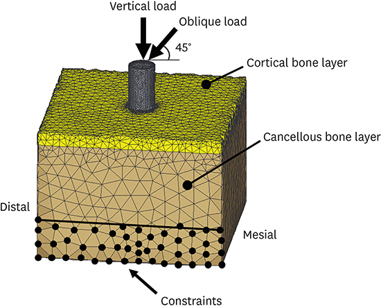
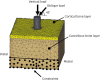
Six artificial bone blocks of solid rigid polyurethane foam (Sawbones, Pacific Research Laboratories, Vashon Island, WA, USA) with a density of 0.32 g/cm3 were used to simulate low- to medium-density cancellous bone [21]. Short fiber-filled epoxy sheets were used as a substitute for cortical bone [35]. Because the mean crestal cortical bone thickness at the implant placement site for the mandible was 1.5–2.2 mm [2223], a sheet with a 2.0-mm thickness was prepared. The artificial bone was rectangular, with dimensions of 30×30×22 mm (Figure 1).
Implant placement
Screw-type implants with a length of 10 mm and diameter of 4.3 mm (NobelReplace Tapered Groovy, Nobel Biocare AB, Göteborg, Sweden) were placed into the artificial bone blocks. All the bone holes for implant placement were prepared according to the manufacturer's instructions by a single operator. For the axial implant model, the implant was placed perpendicular to the block surface. For the tilted implant model, the bone hole was distally inclined at 30° to the axial implant (Figure 1) [2024]. A 2.0-mm twist drill was used first, followed by 3.5- and 4.3-mm taper drills. With reference to previous studies [2526], a total of 6 implants were used: 3 axial implants and 3 tilted implants.
During implant placement, the maximum insertion torque value (ITV) of each implant was measured using a digital torquemeter (STC400CN, Tohnichi, Tokyo, Japan).
According to the manufacturer's recommendation, for the axial implants, straight-type abutments that were 7 mm high (Snappy abutment, Nobel Biocare AB) were connected to the implants and tightened to 35 Ncm using a manual torque wrench. For the tilted implants, 30-degree angulated abutments that were 5 mm high (30-degree multiunit abutment, Nobel Biocare AB) were connected to the implants and tightened to 15 Ncm (Figure 1).
Measurements of abutment displacement
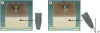
With fixed prostheses supported by implants, the average maximum occlusal force was approximately 200 N for the first premolar and molars [27]. An in vivo study previously demonstrated that the directions of the occlusal load on implants installed at the lower first molar and in the second molar region were approximately vertical and distoinferior, respectively [28]. Vertical and mesiodistal oblique loads at 45° of 200 N were applied to the top of the abutment in all the models using a universal testing machine (FTN1-13A/2000, Aikoh Engineering, Tokyo, Japan) with a head speed of 5 mm/min, and the value of the abutment displacement was recorded. Under vertical and oblique loading, only the lower part of the lateral sides of the cancellous bone layer was clamped with metal plates (Figure 2). Each measurement was repeated 3 times for each artificial bone block and loading direction. The mean of these 3 measurements was taken as the representative value of the loading direction in each specimen.
Finite element model
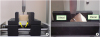
A bone block model corresponding to the dimensions of the experimental samples was constructed using FEA software (Mechanical Finder, version 6.2, Research Center of Computational Mechanics, Tokyo, Japan). Implants with straight abutments 7 mm high and angulated abutments 5 mm high were modeled as a single piece using three-dimensional (3D) modeling software and exported to the FEA software to complete the models (Figure 3). The contact interface between the implant and artificial bone was simulated using the contact elements. To our knowledge, there are no published data on the coefficient of friction between the surface of the oxidized implant used in this study and artificial bone made of polyurethane. Thus, the frictional coefficient for an Al2O2 blasted surface (0.6) was adopted in the present study [29].
Figure 3
Finite element model of the implant, abutment, and artificial bone block. (A) Axial implant model. (B) Tilted implant model.
Patel et al. [30] demonstrated that the Young's modulus of cancellous bone samples was affected by the specimen dimensions and that the Young's modulus of 0.32 g/cm3 polyurethane rigid foam was 66 to 145 MPa. Based on the results of preliminary experiments using both the in vitro loading test and FEA, in which a cancellous bone block without an implant or cortical bone layer was loaded, a Young's modulus value of 66 MPa was assumed for cancellous bone samples. The Young's moduli of epoxy sheets are highly temperature-dependent, ranging from 7.8 GPa (22°C) to 2.8 GPa (37°C) [31]. Thus, a Young's modulus of 6 GPa for epoxy sheets was used considering the temperature during the experimental procedure (approximately 26°C). The implant and abutment were assigned the material properties of titanium. The Poisson's ratio of artificial bone and the material properties of titanium were obtained from previous studies (Table 1)[426]. The material properties were assumed to be homogeneous, isotropic, and linearly elastic. A finite element model was constructed with 4-node tetrahedral elements, and had approximately 140,000 elements and 29,000 nodes.
Table 1
Material properties used in the finite element model

| Materials | Young's modulus (MPa) | Poisson's ratio |
|---|---|---|
| Titanium | 110,000 | 0.35 |
| Artificial cortical bone | 6,000 | 0.30 |
| Artificial cancellous bone | 66 | 0.30 |
A 200-N vertical load and mesiodistal oblique load at 45° were applied. To simulate the constraints in the experimental situation, the boundary conditions were established by the nodes of the lower part of the lateral sides of the model (Figure 4).
Analysis of abutment displacement and micromotion
Nonlinear FEAs were performed to calculate the abutment displacement of the loaded region and micromotion at the bone-implant interface. The micromotion was computed as the relative displacement between 2 nodes (1 node on the bone side and 1 node on the implant side) of elements on the interface.
Evaluation of the in vitro experiment and FEA results
The values of the abutment displacement were compared without conducting a formal statistical analysis because of the low number of samples in the in vitro experiment. Because the results of FEA do not have variance, to evaluate whether the in vitro experiment and FEA results agreed, the relative error was calculated [2532].
Convergence test
A convergence test of the finite element models was performed to verify the mesh quality, and the convergence criterion was set to be less than 1% for changes of the micromotion value. Based on the results of the convergence test, a minimum element size of 0.3 mm was set for meshing.
RESULTS
In vitro experiment
The mean ITV of the axial implants and tilted implants was 55.8±9.2 Ncm and 48.5±5.4 Ncm, respectively.
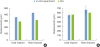
The abutment displacement values of the tilted implants were 18.9% and 21.8% higher than those of the axial implants under vertical loading and under oblique loading, respectively. The abutment displacement values under oblique loading were 53.2% to 56.9% higher than those under vertical loading (Table 2, Figure 5).
Table 2
Abutment displacement (μm) and relative error between the experimental measurements and FEA results

Abutment displacement calculated by FEA
The displacement of the implant and abutment under loading is shown in Figure 6. The axial and tilted implants were displaced inferiorly under vertical loading, whereas they were displaced distally with rotation under oblique loading. The tilted implants showed more rotation than the axial implants.
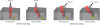
Figure 6
Displacement of the implant and abutment under loading. The artificial bone block, implant, and abutment before deformation are also illustrated. The circles indicate where the maximum micromotion was observed in the model. Yellow arrows indicate the direction of the displacement of the implant relative to the surrounding bone in the apex region.
The abutment displacement values of the tilted implants were 7.3% and 7.9% higher than those of the axial implants under vertical loading and under oblique loading, respectively. The abutment displacement values under oblique loading were 91.7% to 92.7% higher than those under vertical loading (Table 2, Figure 5).
Micromotion at the bone-implant interface
Maximum micromotion was observed at the apex of the implant in all models. Under vertical loading, the implant apex was displaced relative to the surrounding bone inferiorly and mesioinferiorly in the axial implant model and tilted implant model, respectively. Under oblique loading, the relative displacement of the implant apex to bone was in a mesioinferior direction in the axial implant model, whereas it was in a mainly mesial direction in the tilted implant model (Figure 6).
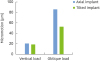
The maximum micromotion values in the axial and tilted implants were very close under vertical loading, whereas in the tilted implant model, the maximum micromotion was 38.7% less than in the axial implant model under oblique loading. Oblique loading showed a 2.8- to 4.1-fold higher maximum micromotion than vertical loading (Figure 7).
DISCUSSION
Primary stability is one of the most important variables that affects the success of immediately loaded implants. The success of dental implants is not related to the timing of loading, but rather to the critical function of micromotion [1]. Previous studies have shown a threshold of micromotion between 50 and 150 μm, above which micromotion induces the formation of fibrous connective tissue, preventing the osseointegration of an immediately loaded implant [33]. Clinically, it is impossible to introduce any device into the bone-implant interface to examine the extent of micromotion during mastication. Therefore, when immediately loading a dental implant, clinicians should employ all possible measures to prevent or reduce micromotion [12].
To evaluate the primary stability of dental implants, many researchers have investigated micromotion using FEA [491112181920]. It should be noted that some assumptions must be made in the finite element model to simulate real conditions, leading to model distortion. For the simulation results to be reliable, it is necessary to verify the results of FEA with experiments [34]. Some authors have examined the validity of finite element models by measuring implant displacement using an experimental model [3536]. In the present study, abutment displacement was evaluated for model validation.
As the results showed satisfactory agreement between both techniques for abutment displacement, the finite element model is considered to be validated. The discrepancies between the experimental and FEA results could be due to the following reasons: 1) the assumptions made in the finite element model; and 2) the inevitable presence of at least a small discrepancy in the loading area and constrained area between the experiment and FEA [34]. The peak ITV might also have influenced the implant displacement [813]. However, the effect of ITV differences is likely to have been negligible, because the ITVs of both the axial and tilted implant groups were close in the present study [13].
The results of the in vitro experiments and FEA showed that the abutment displacement was greater under oblique loading than under axial loading, and greater for tilted implants than for axial implants. These results occurred because axial loading induces better force transmission to the surrounding bone, resulting in less displacement of the implant and abutment [15]. In addition, the oblique load produces a bending moment, leading to greater displacement than occurs with axial loading. Because the loading angle to the implant axis is larger for a tilted implant than for an axial implant, a tilted implant may undergo more displacement than an axial implant.
Maximum micromotion was observed at the apex of the implant, in agreement with previous FEA studies in which low-density cancellous bone models similar to the present finite element model were simulated [1416]. The maximum micromotion value was strongly affected by the loading direction, which is partially consistent with the results reported by Hsu et al. [19], who found that the maximum micromotion was approximately 5- to 7-fold higher under 45° oblique loading than under vertical loading. The discrepancy between the results of the present study (2.8- to 4.1-fold) and those of Hsu et al. [19] might be explained by the differences in the model geometry and material properties used in the FEA.
Abutment displacement is the result of the micromotion and deformation of bone. Under vertical loading, the abutment displacement directly correlates to the implant displacement, and thus, most of the applied load contributes to bone deformation. By contrast, abutment displacement does not represent implant displacement under oblique loading conditions because the implant may rotate. Therefore, obliquely loaded abutments might contribute to bone deformation and the additional sliding movement of the implant in bone [15]. The maximum micromotion values under vertical loading were low, regardless of the implant insertion angle, for the above reasons. Unexpectedly, under oblique loading, the tilted implants showed less micromotion than the axial implants, although the tilted implants induced a greater abutment displacement than the axial implants. This result is probably because of the difference in the modality of the displacement of the implant; rotational motion rather than sliding movement in the tilted implant model might lead to less micromotion than occurred with the axial implant model.
The biomechanical effects of implant tilting have been previously investigated [243738]. Tilted implants usually transmit more stress to the surrounding bone than axial implants [37]. However, the use of tilted implants in a full-arch fixed prosthesis allows the distal cantilever to be reduced and decreases peri-implant bone stress [2438]. The micromotion values might also be affected by the cantilever length. Meanwhile, when an implant is part of a multiple implant-supported prosthesis, the spread of the implants and the rigidity of the prosthesis will reduce the bending of the implants for both of axial and tilted implants, resulting in less micromotion. Further studies are necessary to clarify whether tilting the distal implant is advantageous for reducing micromotion in multiple implant-supported restorations.
Several techniques have been used to assess primary stability, including the insertion torque, removal torque, cutting torque, Periotest values, and resonance frequency analysis. To date, implant/abutment displacement has been investigated as an important indicator of primary stability in previous in vitro studies [8101315]. Measuring the displacement of implants seems to be the most reliable method, as described in the literature [10]. However, the relationship between abutment displacement and micromotion varied according to the loading direction (vertical or oblique) as well as the implant insertion angle (axial or tilted). Therefore, the absolute abutment/implant displacement should be interpreted with care when evaluating primary stability.
Some limitations are associated with the present FEA and the in vitro experiment. An important limitation is that in modeling the interface between the implant and bone, perfect contact with friction was assumed, which can influence the biomechanical behavior of implants, although nonlinear finite element contact analysis was used to assess the stress/strain of immediately loaded implants [39]. This study used single-implant models with a specific bone density and cortical thickness, and only limited loading conditions were simulated. Moreover, only a small number of artificial bone samples were tested in the in vitro experiment. Further, the material properties of the bone models were assumed to be homogeneous and isotropic, which does not correspond to clinical reality.
In conclusion, tilted implants may have a lower maximum extent of micromotion than axial implants under mesiodistal oblique loading. The maximum micromotion values were strongly influenced by the loading direction. The relationship between abutment displacement and micromotion varied according to the loading direction and the implant insertion angle.
 XML Download