

 PDF
PDF ePub
ePub Citation
 Print
Print


INTRODUCTION
Heat-polymerization polymethyl methacrylate (PMMA) denture base deforms during polymerization, cooling, and finishing, resulting in linear deformation of 0.45 – 0.9%.12 The fit between denture base and mucosal tissue is important for the retention of complete denture. Deformation and shrinkage affect the retention, stabilization, and support of complete denture, thus affecting patients' satisfaction and quality of life.3
To fabricate complete denture, conventional method was developed approximately 80 years ago.4 To overcome and compensate for such polymerization shrinkage, many studies have been performed, including denture base materials, fabrication methods, and clinical protocols such as laboratory re-mounting procedure.567 To solve dimensional inaccuracy of the compression molding method, Pryor has attempted a pressure injection molding method in which the un-polymerized acrylic resin was injected into the mold.8 In the 1970s, Ivoclar (Schaan, Liechtenstein) introduced a pressure injection molding method with improved resin. Since then, many companies have introduced pressure injection molding methods. Such methods are now commonly used in the fabrication of complete dentures.9 However, most of these studies and methods have been conducted within the framework of traditional methods.
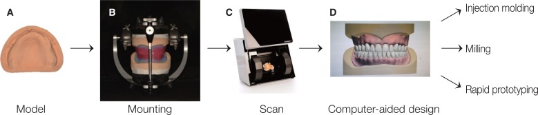
In the last 20 years, computer-aided design (CAD) and computer-aided manufacturing (CAM) technology has been broadly used in the dental field for manufacturing various prostheses due to its advantages such as increased efficiency, automaticity, and accuracy of the entire treatment flow. Fabrication of complete denture by CAD/CAM procedure has been realized and progressed by the development of digital devices and CAD software.101112 Maeda et al. have reported the first scientific report describing the CAD/CAM procedure for fabricating a complete denture.13 When manufacturing a complete denture using digital workflow, the process begins with digital scanning of the edentulous arch, including challenging areas for the intraoral scanner device to scan, which are movable areas such as non-keratinized tissue and smooth surfaces covered with saliva.1314 Many researches have been inclined to scan the edentulous master cast using an extraoral scanner.15 After digitalization of conventional impression, complete denture can be designed using CAD software. The fabricating of the denture base or the entire complete denture can be processed by either milling or rapid prototyping (RP) with a 3D printer.
The base of the complete denture is essential for its retention. Clinical treatment results are greatly influenced by the accuracy of the base.3 Computer numerical control (CNC) machines have been used in many studies to fabricate high accuracy denture bases.111617 Avadent and Dentca, the first two companies that commercialized CAD/CAM dentures, were taking different approaches for fabricating method, milling, and 3D printing. These technological advancements have provided competent methods to facilitate fast and accurate fabrication of bases. Goodacre et al.18 have compared the fit of the base made by heat compression, fluid resin, injection molding, and CAD/CAM milling methods and found that the CAD/CAM milling method is accurate and reproducible. McLaughlin et al.19 have compared the deformation of denture bases manufactured by three methods: compression molding, injection molding, and CAD/CAM milling. The influence on shrinkage by arch shape and palate depth was also studied. They found that well and equally fitted dentures were produced by injection molding and CAD/CAM milling methods, and both methods showed better fit accuracy than compression molding method.19 Many other studies have also compared the accuracy of bases fabricated by conventional manufacturing methods and milling methods. However, research on the accuracy of the base made by RP method using 3D printers is insufficient.
Therefore, the aim of this study was to evaluate the accuracy and surface resolution of denture bases fabricated by three methods: injection molding, milling, and RP using surface matching software. The null hypothesis was that there would be no difference in the accuracy or resolution among denture bases fabricated with the three methods.
MATERIALS AND METHODS
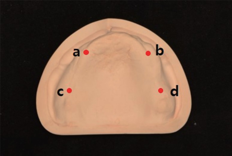
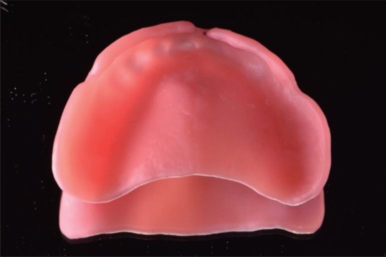
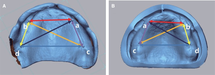
Thirty maxillary complete denture bases (10 denture bases for each group, 3 groups) were fabricated and evaluated (Fig. 1). For the master cast of this study, medium palate depth (12 mm palate depth) was selected according to palate depth classification of edentulous patient described by Johnson et al.20 In the master cast, right and left points crossed anterior alveolar ridge and posterior alveolar ridges and points on posterior alveolar ridge were 15 mm in distance, parallel to the midpalatal suture from right and left hamular notches that were engraved 1 mm diameter using No. 2 carbide round bur (Burstar, Alphadent, Goyang, Korea) (Fig. 2). The master cast with index notches was duplicated and ten casts were fabricated using silicone (Deguform, Dentsply international, Hanau, Germany) and type IV gypsum (GC FujiRock, GC Europe, Leuven, Belgium) according to the manufacturers' instructions. Using a record base and a record rim, casts were mounted on a semi-adjustable articulator based on the fact that Korean edentulous patients had an average value of 23 mm from anterior border to the occlusal surface for the maxilla and 18 mm for the mandible. After scanning mounted casts with a record base and a record rim using a model scanner (D800, 3Shape A/S., Copenhagen, Denmark), the denture base was designed, including denture polished surface and intaglio surface. Artificial teeth alignment was performed using CAD software (3shape dental designer, 3Shape A/S, Copenhagen, Denmark). The denture base of the palate was designed in standardized form (2 mm in thickness). Denture bases for the three groups were fabricated based on same standard tessellation language (STL) files designed in the CAD software (Fig. 1).
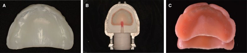
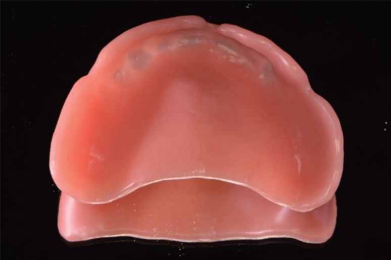
In the injection molding method group, wax block (Mazic wax, Vericom, Daejeon, Korea) was milled based on the STL file designed in the CAD software and the base was fabricated using an Ivocap injection system (Ivoclar Vivadent AG, Schaan, Liechtenstein) with PMMA resin (SR-Ivocap high impact, Ivoclar Vivadent AG) (Fig. 3). For the milling method group, denture bases were fabricated with CAD/CAM milling using CAM software (HyperDent, FOLLOW-ME! Technology, Munich, Germany) and a 5-axis milling machine (ARUM 5X-200, Doowon, Daejeon, Korea). A PMMA block (Vipi block GUM, Vipi, São Paulo, Brazil) of 98.5 mm in diameter and 25 mm in height was milled in wet condition with a minimum bur size of 1 mm while connectors were set to 10 (Fig. 4). For the RP method group, denture base resin (NextDent Base, NextDent, Soesterberg, Netherlands) was mixed during 1 hour using a stirring device (LC-3D Mixer, NextDent, Soesterberg, Netherlands) before printing process according to the manufacturers' instruction and checked for stable color of resin. Denture bases were vertically stacked with approved denture base material at a speed of 10 to 30 mm/h using a digital light processing (DLP) 3D printer (Bio3D. W1, Bio3D Inc., Seoul, Korea). After completion of the printing process, denture bases were removed from the platform and cleaned with 99% isopropyl alcohol in an ultrasonic cleaner for 5 minutes followed by post curing for 15 minutes using an ultraviolet curing unit (LC-3D Print Box, NextDent, Soesterberg, Netherlands) (Fig. 5). After processing, denture bases of all groups were hydrated for 24 hours.
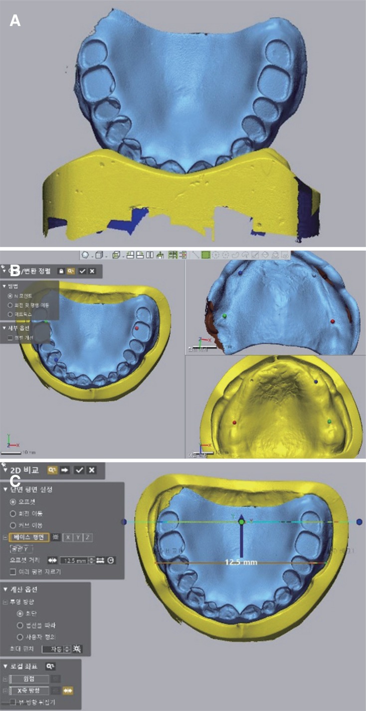
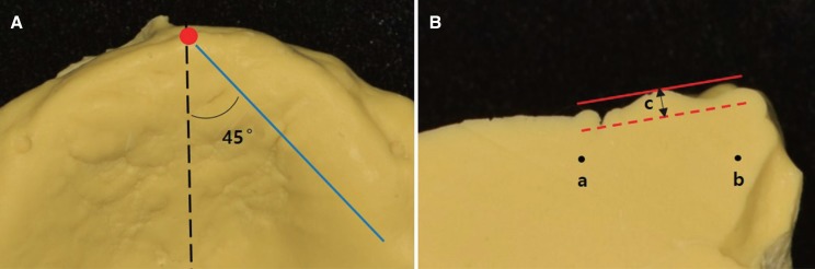
The left posterior border of the denture base was fixed with gypsum and coated with anti-glare spray (Cerec Optispray, Sirona dental systems, Bensheim, Germany). Casts and intaglio surfaces of denture bases were scanned with a model scanner (Rainbow scanner prime, Dentium, Suwon, Korea) and recorded as STL files. To determine the overall deformation of the base in the horizontal direction, the distance between 4 notches was measured. The most convex point of notches in the denture base and the most concave point of notches in the cast were used. Distance values between a-b, c-d, a-c, b-d, a-d, and b-c were measured with a surface matching software (Geomagic control X, 3D systems Inc., Rock-hill, SC, USA) (Fig. 6). Absolute values of the distance between the intaglio surface of the denture base and the cast were measured with the surface matching software. In this software, four notches of the denture base and the cast with an overlay guide were used to fit the denture base on the cast (Fig. 7). Two cross sections were made with the plane passing through the right and left 2nd upper premolar and the right and left 2nd upper molar. Absolute values of the distance between the intaglio surface of the denture base were measured in each group at the intersection of two cross sections and the midpalatal suture. The palatine rugae resolution was evaluated by measuring the vertical distance between the most prominent point and the deepest point. The intaglio surface of the denture base in each group was impressed with polyvinylsiloxane impression materials (Imprint II Garant light body, 3M ESPE, St. Paul, MN, USA). From the forefront point of the midpalatal suture of the impression body, the plane was cut at an angle of 45° with the midpalatal suture. The cross section was photographed by setting the camera at the shooting angle of 90° with respect to the cross section. On the photograph, a line was drawn by connecting the upper part of one end and the upper part of the other end of the palatine rugae. Another line was drawn parallel to the line at the lowest point of the palatine rugae. The vertical distance between the most prominent point and this line was measured using Adobe Photoshop CC 2015 (Adobe Systems Inc., San Jose, CA, USA). Before photographing, two arbitrary points were displayed on the impression body. The ratio between the actual distance and the distance in the photograph was measured and applied to the vertical distance value in order to calculate the actual vertical distance value (Fig. 8). The entire measurement procedure was performed by one tester.
Results were analyzed using IBM SPSS Version 21.0 for WIN (SPSS Inc., Chicago, IL, USA). All data were subjected to normality and homogeneity of variance on a Shapiro-Wilk test for each group. One-way analysis of variance (ANOVA) with post hoc Tukey's honestly significant difference (HSD) was performed. The significance level was set at 5%.
RESULTS
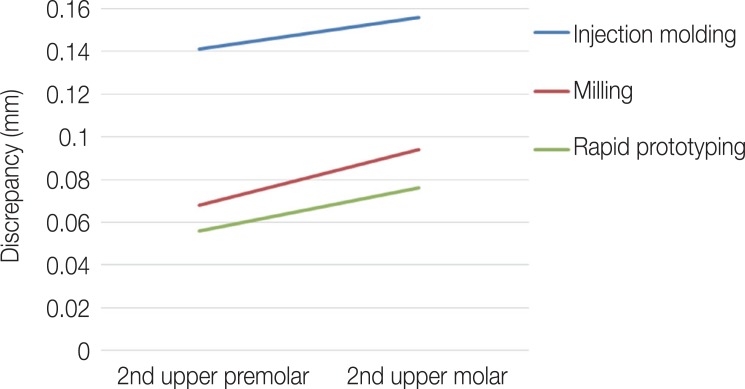
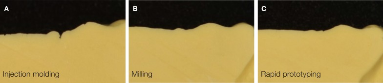
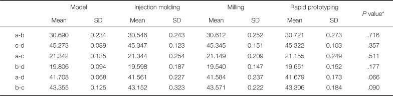
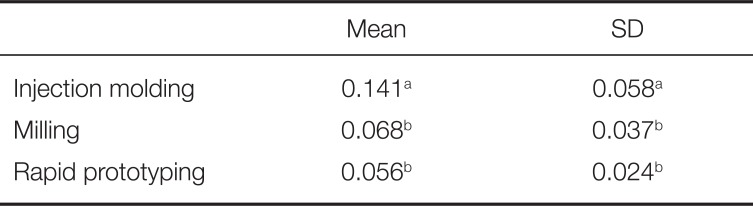
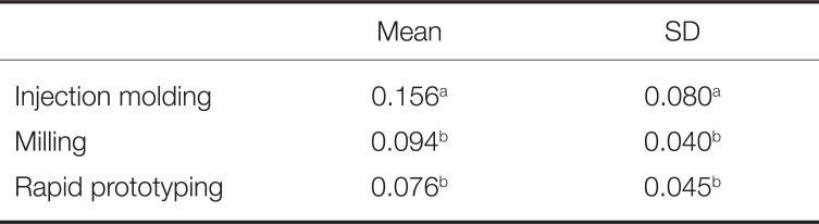
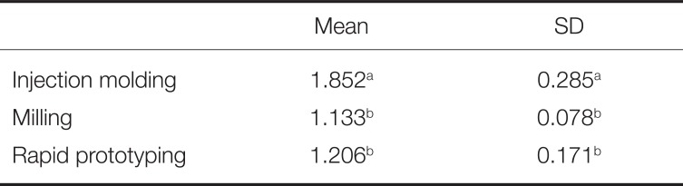
One-way ANOVA showed no significant (P > .05) effect of a fabricating method on the overall deformation of the base in the horizontal direction, leading to the acceptance of the null hypothesis regarding the distance between 4 notches (Table 1). However, the null hypothesis for the fit accuracy in two points where the 2nd upper premolar and the 2nd upper molar crossed the midpalatal suture was rejected. There was no significant (P = .94) interaction effect between the two factors of fabricating method and the region (2nd upper premolar and the 2nd upper molar) of the midpalatal suture (Fig. 9). There were statistically significant differences in the point where the 2nd upper premolar crossed the midpalatal suture. The fit accuracy of the injection molding method was lower (P < .05) than that of other methods (Table 2). At the point where the 2nd upper molar crossed the midpalatal suture, the injection molding method also had significantly (P < .05) lower fit accuracy than the other methods (Table 3). The mean value of discrepancies between the denture base and the cast in the midpalatal suture was found to be the lowest for those fabricated by the RP method, followed by those fabricated with the milling method and the injection molding method. The palatine rugae resolution was different by fabricating method. Milling and RP methods were similar while injection molding method had higher resolution (Fig. 10). The degree of the palatine rugae resolution was evaluated by measuring the vertical distance between the highest point and the lowest point. It was significantly (P < .05) higher in the injection molding method than that in the milling or RP method (Table 4).
DISCUSSION
In all prostheses manufacturing, accuracy is the most important issue for clinicians. Shrinkage from polymerization has been inevitable since the introduction of polymer into the manufacturing of denture bases. For accuracy of prosthesis manufacturing, it is necessary to check the overall size and the fit of the intaglio surface.
There was no statistical significance in the amount of deformation of the base in the horizontal direction through the measurement of the distances between notches on the ridge. There was no difference in the accuracy of the overall size for each method, and the RP method, which has not been studied much, has not disclosed much deformation when making the complete denture base. There was no difference in the accuracy of the overall size for each method.
According to studies on fabricating methods for maxillary complete denture, the misfit of the base varies depending on the region.21 The gap between the denture base and the cast is generally influenced by shrinkage of the resin material during polymerization with a tendency of the internal stress toward the central region of the denture base and subsequent distortion caused by limitation due to the surface shape of the alveolar ridge.22 Therefore, in the central area of the posterior border and buccal vestibule area, the largest gap is generally measured when close contact state was maintained around the ridge crest.23 In the present study, the discrepancy was measured on the 2nd upper premolar, the center of anteroposterior distance, the 2nd upper molar, posterior region, points crossing, and the midpalatal suture.
Recently, many studies have compared the accuracy between CAD/CAM milling and conventional methods. According to the study of Goodacre et al.,18 the CAD/CAM milling method showed less misfit than the injection molding method in the maxillary complete denture, including the edge of denture border, 6 mm away from denture border, palate, posterior palatal seal area, and crest of alveolar ridge. Steinmassl et al.24 have compared the congruence of the compression molding method and various CAD/CAM milling systems in various regions of the maxillary complete denture. CAD/CAM milling systems had higher congruence with denture-bearing tissues than compression molding methods. In conventional and almost all CAD/CAM systems, alveolar ridge and palate is the most accurate fit region, and posterior palatal seal and anterior and lateral seal regions showed the largest extent of misfit.24
In injection molding method, as mentioned in many previous researches, the misfit due to the polymerization shrinkage and the internal stress after the polymerization is relatively high in the midpalatal suture area because of the shape and the position. While conventional methods using PMMA should consider polymerization shrinkage, the milling method is processed by subtraction of an industrially pre-polymerized PMMA blank (puck) that has final dimension. There is no dimensional deformation of the denture base, theoretically. Thus, milling is the most reproducible technique. In the present study, the congruence of the base fabricated by the milling method was mainly influenced by the accuracy of the scanner used for the measurement and the precision of the milling process. Two types of model scanners were used; D800 model scanner was used to scan mounted casts for designing denture and Rainbow scanner prime was used to scan the manufactured denture bases of each group. Each of the two procedures was independent and the results was measured and analyzed from scanning with same model scanner, Rainbow scanner prime. According to the manufacturer, Rainbow scanner prime has accuracy within 10 µm. Since the amount of the misfit was larger than the scanner's accuracy, the experimental setup and measurement in this study appeared to be appropriate for measuring differences. An additional error could be caused by the powder that coated the denture base for scanning. Schaefer et al.25 have addressed that marginal fit and internal adaptation in partial coverage restorations were adversely effected by the powder for scanning. However, in the same report, deviations were within clinically acceptable thresholds. In vitro studies of coating powder have shown that surface pre-treatment with powder does not significantly decreased the scanning accuracy26 because of small particle size of aerosol sprays around 5 µm.25 Although this error may be considered in the field of fixed prosthodontics and inaccuracies of degree of micrometer are considered clinically acceptable in the field of complete denture prosthodontics, this hypothesis must be scientifically proven. Considering the reason of additional misfit, the milling process can be affected by a milling bur, the characteristic of the area to be milled, and the machining axis. Steinmassl et al.24 have reported that the major challenge in the milling method may be reproducing undercut regions, based on their finding that all CAD/CAM denture systems have some problems in reproducing the anterior and lateral denture border area that often include undercut regions below the alveolar crest.
Stereolithography is one of RP methods. The advantage of this technology is flexibility due to the range of available machines, low percentage of wasted raw material, and ability to print complex geometries. The main problems of printing method are staircase effect, low reproducibility, and the necessity of supporting structures. These supporting structures need additional material and time.27 The main difference between stereolithography and DLP is the light source. Arc lamp or digital micromirror device and small micromirrors attached in a matrix on a semiconductor chip create the image in DLP. Each micromirror reflects one or more pixels in the projected image. The resolution of the image is proportional to the number of micromirrors.28 Discrepancies of the RP method can be incorporated in each step, including designing in the CAD software, slicing procedure in the printing software, and printing. The accuracy of printed object is influenced by many various factors such as light intensity, direction and angle of printing,2930 number of layers,31 software,32 shrinkage between layers,30 amount of supporting structure,29 and post processing procedures. Each material has its own activation range, wavelength, intensity, and exposure time in each 3D printer and not all printing materials are compatible with all 3D printers. Because of disparities in protocol (selected technology, parameters of printers, and the material used for printing), it is very difficult to compare the results of various studies.33
In the RP method group, discrepancy values in the palatal region (0.056 ± 0.024 mm on 2nd upper premolar, and 0.076 ± 0.045 mm on 2nd upper molar) were very low. There are few studies on the fit of the denture base fabricated by the RP method. It is currently unknown in exactly which process the error occurs due to complexity of the printing process and uncontrolled recoveries of duplicated errors. However, the possibility of using the RP method with considerable accuracy was confirmed through the present study.
Light-cured acrylic resins for fabricating the denture base are available on the 3D printer. There are a few products licensed for use in patients. The NextDent Base used in this study is FDA approved. The safety of these RP acrylic materials is being tested and these materials are being assessed for long-term use. In this base material, post curing is done for 30 minutes under certain conditions following the instructions for use. However, in this study, 15 minutes was performed with different polymerization conditions in order to correct the accuracy. In the case of less polymerization, the leakage of residual monomers or decreasing strength and the color of the fabricated denture may be insufficient. However, there was sufficient polymerization in the confirmation of the denture base color in this study.
There was a high possibility of no interaction effect between the fabricating method and the measurement point in the midpalatal suture through parallel tendency of not crossing each graph on the profile chart (Fig. 9). Generally, there is a difference in the misfit for each method depending on the region due to characteristics of the fabricating method. However, effects by each fabricating method on two points measured in this study were almost equal. According to McLaughlin et al., the effect of the palate depth (palatal depth of 12 mm and 18 mm classified by Johnson et al.20) on the misfit by manufacturing method (conventional method and CAD/CAM milling method) was not observed.19 In the present study, the palatal depth of the cast was 12 mm and the palatal depth did not influence the results.
The misfit in conventional measuring method is determined by measuring the actual misfit after cutting21 or using a device such as computed tomography after fitting the denture on the cast.23 The development of CAD software makes it possible to easily identify the cross-section of the desired region of the program. The measurement of the misfit using the CAD software sometimes displays a negative value, which is different from the conventional method because the denture base image is fitted to the cast based on the reference points. In this study, statistical analysis was performed for absolute values of the measurement to eliminate errors due to negative values. Because this method is different from fitting the denture to the patient, it is difficult to interpret clinically. However, it is more meaningful in measuring the accuracy of the fabricated denture itself. By measuring the discrepancy, it is possible to improve the convenience and perfection of the clinical procedure by fabricating more accurate dentures and predicting areas where errors may occur.
In comparison with the degree of palatine rugae resolution of the intaglio surface of the base, the injection molding method was found to be the most precise method. The accuracy of the 3Shape D800 scanner was 7 – 8 µm. When light was used for scanning, specific areas in the palatine rugae of the cast might not have been scanned. In the milling method, the size of milling bar and undercuts for the axis of milling bar are limited. The intaglio surface of a CAD/CAM milled denture is not as smooth as the intaglio surface of the base fabricated by conventional method and is rather layered than conventional method. Goodacre et al.'s study also has shown similar texture on the intaglio surface images.1834 This surface shape is inevitable because milling bar is larger than the size of stone particle. The resolution of the Bio3D. W11 DLP 3D printer used in this study was 57 µm and 50 to 100 µm for the one layer. The resolution is the smallest or the finest degree that could be reproduced by the 3D printer and it is specific for each 3D printer. The resolution should be defined in µm or dots per inch (dpi) for each x, y, and z-axis and generally, the z-axis corresponds to the thickness of the layer.35 These resolutions can be confirmed simply by the shape, but in this study, the vertical distance between the highest point and the lowest point was measured and quantified.
The limitation of this study includes difficulty in confirming the error in each stage of the 3D printing procedure because of complicating factors. Future research is needed to confirm the error in each stage and overcome it. Clinicians who are concerned with the CAD/CAM milling and 3D printing technique for fabricating a complete denture may obtain clinically acceptable fit accuracy and retention. With generally equivalent fit accuracy between the milling and RP methods of the CAD/CAM work flow, other factors such as cost, mechanical property, risk of the residual monomer, color stability, ease of fabrication, and clinical application might need to be considered. Future studies should evaluate these factors in order to use CAD/CAM technology more stably and accurately.
CONCLUSION
There was no significant difference in the overall deformation in the horizontal direction among the three methods through comparison of distances between the 4 notches of the ridge. Comparison of fit accuracy between the cast and the maxillary complete denture base was evaluated on the 2nd upper premolar and the 2nd upper molar crossing the midpalatal suture, showing relatively high deformation in the conventional method due to polymerization shrinkage and the internal stress. The mean value of discrepancies was the lowest in the RP method, followed by that in the milling method and the injection molding method. The injection molding method had significantly lower fit accuracy than the other two CAD/CAM methods at two points. The degree of resolution was evaluated by measuring the vertical distance between the highest point and the lowest point in the palatine rugae area because of the complexity of the architecture. The injection molding method had significantly higher resolution than the milling method and the RP method.
 XML Download