

 PDF
PDF ePub
ePub Citation
 Print
Print


INTRODUCTION
Maxillary complete dentures are an economic and easy treatment modality for edentulous patients and are still widely used. However, these dentures are associated with various complications from which fractures are often encountered.1 The average proportion for fracture of a removable polymer-based denture has been reported to be up to 68%.2-4 Midline fractures appear to be one of the most common problems in maxillary complete dentures.3,5 It was reported that denture teeth is the most common fracture site (33%), followed by the midline fracture of complete dentures (29%).6 The hard palatal midline causes a seesaw situation when dentures are not relined, since there is ongoing crestal resorption.
Most of the fractures in maxillary complete dentures occur due to fatigue and/or impact.6 The fatigue is mainly caused by flexural fatigue occurring due to repeated flexing of the base of the denture. The fracture follows microscopic cracks in positions where the stress concentrates.7 The distribution of stresses on maxillary complete dentures can be analyzed experimentally in many ways such as photo elastic models,8 strain gauges,9 holography10 or finite element modeling11,12 It has been shown that the stress concentrates on the anterior palatal areas of maxillary dentures rather than the posterior regions and the midline fractures of the maxillary complete denture always start from the anterior stress field.9 A finite element analysis (FEA) study speculated that the buccal placement of the occlusal contacts of the artificial teeth may play a role in the fatigue fracture of the complete maxillary denture.13 Moreover; sharp frenal notches, midline diastema and palatal tori could be additional causes for midline fractures of maxillary complete dentures.4,14,12,15 Based on clinical experience and empiricism, it can be hypothesized that frenal notches lead to fracture of complete dentures, too. Several finite element stress analyses studies have been performed to investigate the stress-concentrating effect of a frenal notches. It was found that a large frenal notch resulted in high stress levels11,12 and the greatest stress concentration was observed in the labial frenum notch.16 It was pointed out to the probable rise of stress with an increase in the size of the labial frenulum notch.
The purpose of this study was to evaluate the influence of the height of frenulae on stress accumulation in the maxillary complete dentures.
MATERIAL AND METHODS
A maxillary complete denture was fabricated on an edentulous maxillary simulation model (Kavo OK UB H, Kavo GmbH, Biberach/Riss, Germany). In order to mimic soft tissue, a silicone (Affinis light body, Coltene/Whaledent AG, Altstätten, Switzerland) layer of 3 mm thickness was fabricated. First, the model was boxed with dental modeling wax (Cavex Set Up Waxes, Cavex, Haarlem, The Netherlands) and poured with dental stone (Moldano Dental Stone, Bayer Co., Leverkusen, Germany) which later was covered with dental modeling wax of 3 mm thickness and checked by a periodontal probe in all areas, ensuring an uniform thickness. A mixing tip of light viscosity silicone was attached to the palatal seal area. The wax was covered with a plaster layer of 4 cm. After separation of the covering plaster layer and removal of the wax, the plaster cover was relocated and a light viscosity silicone impression material was injected via the mixing tip into the space between the model and the plaster cover (Affinis light body, Coltene/Whaledent AG, Altstätten, Switzerland). After the setting of the impression material the mold was separated and excess material was trimmed. An alginate impression was made (Kromopan, LASCOD SpA, Firenze, Italy) and poured with type III dental stone (Moldano Dental. Stone, Bayer Co., Leverkusen, Germany). The base material of the denture was autopolymerizing polymer according to the manufacturer's instructions and left on the bench for final polymerization (Paladent RR, Heraeus Kulzer GmbH, Hanau, Germany). After completion of the trimming and polishing procedure of the first maxillary complete denture, seven duplicates for each group, 32 maxillary complete dentures in total,were obtained with a previously published technique.17 The production of the dentures was performed in the same flask which had a silicone lining to allow multiple use of the same mold. Each denture was polymerized under the same conditions, such as the pressure, and checked with a caliper for analogy before including in the testing procedures.
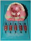
The strains were measured with five strain gauges on different locations and the stresses were calculated. The rosette strain gauges (CEA 125UR, 350Ω, Vishay Precision Group Inc., Malvern, PA, USA) were bonded on to the polished surface of the complete maxillary denture with a cyanoacrylate-based adhesive (Vishay Measurements Group, Strain-Gauge Bonding Adhesive, Vishay precision Group Inc., Malvern, PA, USA). Gauge 1 was bonded onto palatal incline of the first molar tooth. Gauge 2 was bonded onto the midline of the denture near to the singulum of two central incisors and on the incisive papilla. Gauge 3 was bonded onto midline lying on the line crossing through the first molars mesio-lingual cusp tips. Gauge 4 was bonded onto the midline in the palatal seal area. Gauge 5 was bonded on the opposite palatal incline of the first molar tooth (Fig. 1). The whole system was loaded via the universal testing machine (MTS Bionix-II Axial/Torsional Test System, MTS, MN, USA) under quasi-static loading conditions. A preload of 10 N was applied to the model to account for model geometry irregularities due to the method of production. To mimic occlusal forces bilaterally 110 N of total load was applied from the premolar and molar region superimposed over the 10 N preload. The loading procedure was repeated 11 times for each denture and each frenulum height. Loading data was in real-time output to strain-gage conditioning and data acquisition system (P8048 High Channel Count Data Acquisition System, PROSIG Ltd, Hampshire, UK) for synchronous recording of strain and loading data. Recorded strains were than post processed using laws of linear elasticity to obtain von Mises stress values as well as other strain and stress components. Modulus of elasticity was taken to be 1960 MPa and Poisson's ratio was taken as 0.3 as material parameters of PMMA in this study.
To examine the effect of the buccal frenulum height on the stress field of each maxillary complete denture, four different frenulum heights were generated. The height of denture base from the end of frenulum to the peak of the papilla was prepared 11 (Group A), 8 (Group B), 5 (Group C) and 2 mm (Group D) respectively in all dentures by grinding with a low speed hand-piece. The same procedure was repeated for the other dentures.
Statistical analyses were utilized in this study to assess the results of the in vitro tests. For the statistical analysis of the results the NCSS 2007 & PASS 2008 Statistical Software (Kaysville, UT, USA) was used. The Kruskal Wallis test was used for the comparison of calculated stress values of different groups. To determine the group engendering the difference the Post hoc Mann Whitney U test was used. The results were assessed at a 95% confidence interval, at a significance level of P<.05.
RESULTS
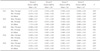
The mean value of the eleven consecutive test results of the eight dentures, measured at each strain gauge, for each frenulum height group is shown in Table 1.
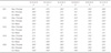
A statistically significant association between the height of the labial frenulum and the calculated stresses and strains was shown (Table 1 and Table 2), predominantly in the midline and especially in gauge number 2, situated on the incisive papilla.
Strain Gauge 1 (SG 1)
There was a statistically significant difference between the maximum and minimum principal stress values of the groups (Table 1). The maximum principal stress values of Group D were significantly higher than Group A, B and C. There was no statistically significant difference between the maximum principal stress values of the other groups (Table 2). The minimum principal stress values of Group D and Group A have been statistically significant lower than Group B and C. There was no statistically significant difference between the minimum principal stress values of the other groups (Table 2).
There was a statistically significant difference between the von Mises values of the groups (Table 1). The von Mises values of Group D were significantly higher than Group A, B and C. The von Mises values of Group A have been significantly higher than Group B. There was no statistically significant difference between the von Mises values of the other groups (Table 2).
Strain Gauge 2 (SG 2)
There was a statistically significant difference between the maximum and minimum principal stress values of the groups (Table 1). The maximum and minimum principal stress values of Group D were significantly higher than Group A, B and C. The maximum principal stress values of Group C have been statistically significant higher than the Group A and B. The maximum principal stress values of Group B have been statistically significant higher than the Group A (Table 2). The minimum principal stress values of Group D have been significantly higher than Group A, B and C. The minimum principal stress values of Group D have been significantly lower than Group B and C. The minimum principal stress values of Group B have been significantly lower than Group C (Table 2).
There was a statistically significant difference between the von Mises values of the groups (Table 1). The von Mises values of Group D were significantly higher than Group A, B and C. The von Mises values of Group C have been significantly higher than the Group A and B. The von Mises values of Group B have been significantly higher than the Group A (Table 2).
Strain Gauge 3 (SG 3)
There was no statistically significant difference between the von Mises, as well as the maximum and minimum principal stress values of all groups (Table 1).
Strain Gauge 4 (SG 4)
There was a statistically significant difference between the maximum and minimum principal stress values of the groups (Table 1). The maximum principal stress values of Group D were significantly higher than Group A, B and C. The maximum principal stress values of Group C was significantly higher than Group A and B. There was no statistically significant difference between the maximum principal stress values of the other groups (Table 2).
The minimum principal stress values of Group D and Group A have been statistically significant lower than Group B and C. There was no statistically significant difference between the minimum principal stress values of the groups (Table 1).
There was a statistically significant difference between the von Mises values of the groups (Table 1). The von Mises values of Group D were significantly higher than Group A, B and C. The von Mises values of Group C have been significantly higher than the Group A and B. There was no statistically significant difference between the von Mises values of Group B and Group A (Table 2).
Strain Gauge 5 (SG 5)
There was a statistically significant difference between the maximum and minimum principal stress values of the groups (Table 1). The maximum principal stress values of Group A were significantly higher than Group B, C and D. The maximum principal stress values of Group D was significantly higher than Group B. There was no statistically significant difference between the maximum principal stress values of the Group B and C, and Group C and D (Table 2).
The minimum principal stress values of Group D have been significantly higher than Group A, B and C. The minimum principal stress values of Group C have been statistically significant higher than Group A and B. There was no statistically significant difference between the minimum principal stress values of Group A and B (Table 2).
There was a statistically significant difference between the von Mises values of the groups (Table 1). The von Mises values of Group A was significantly higher than Group B, C and D. The von Mises values of Group A have been significantly higher than Group B. The von Mises values of Group B have been significantly higher than Group C and D. The von Mises values of Group C were statistically significant higher than Group D (Table 2).
While the negative values seen in the tables represent compression, positive digits stand for tension. Detailed analysis of the data show that in all situations the gauge 3 (the middle of the midline) shows compression. On the other hand, gauges 1, 4 and 5 show compression as minimum principal stress and tension as maximum principal stress. In gauge 2, a very demonstrative behavior could be seen: in Group D experiments the maximum as well as minimum principal stresses had been of tensile nature. The gauges 2 (anterior midline) and 4 (posterior midline) showed a rise in maximum principal stress and von Mises values with growing frenulum size.
The higher the frenulum was, the narrower the denture base had become and the dependant strains and calculated stresses in the anterior and posterior stress fields had risen.
DISCUSSION
The aim of this in vitro study was to determine the role of the height of the labial frenulae in stress accumulation in the maxillary complete denture.
One of the most widely used materials in prosthetic dentistry is polymethyl methacrylate. Since its first use in dentistry, it is being used efficiently as a material for denture bases, artificial teeth or impression trays. However, the primary problem with that material is its poor strength characteristics such as low impact strength and low fatigue resistance.18
The causes of fractures have been studied to find ways to improve denture performance during service.2,13,19 It was pointed out to the importance of occlusal contacts of the artificial teeth which may play a role in the fatigue,13 additionally sharp notches, diastema and palatal tori as potential causes for midline fractures of maxillary complete dentures.4,12,14,15
Strain gauge analysis is a commonly used method in dentistry for biomechanical force measurement.20,21 Although it had been shown that the tip of the incisal notch behind the 2 central incisors was a strain concentration area,11,22 it is not possible to make measurements of the strain because the area on the palatal surface is not flat, and this precludes the placement of strain gauges. Similarly, in the present study, the stress was measured on the incisive papilla area, which was the nearest possible position to the notch ending. The strain concentrations were reported to concentrate primarily along the midline of the denture on the cameo surface,11,22 parallel to our findings. Their occurrence may be in relation to the thin and less compressible mucosa, as well as the hard and prominent midpalatal bone.
The stress along the midpalate is higher because the thin mucosa, supported by a hard central bearing bone, is less compressible3 and becomes a fulcrum point for denture bending.23 The cameo surface opposite the fulcrum point is usually subjected to tensile strain. In the present study, the mucosa was mimicked by a silicone layer of 3 mm thickness. In contrast to previous studies,20 the artificial mucosa was of uniform thickness. This could be a limitation of the present study since the hard midline could not be imitated in this manner. However, the results showed that the stresses accumulated in the incisal notch and posterior midline ending of the denture base nonetheless.
In a recent FEA study,11 the labial frenal notch was found to exhibit the highest compressive strain. The results of the mentioned FEA study indicated a similar behavior as in the present study. The tensile stresses were accumulated in the posterior, but especially in the anterior midline over the incisive papilla. In an early survey, it was observed that a deep labial frenal notch was the cause of midline fractures.4 Compressive strain has a tendency to close the crack, and it is therefore not likely that the crack initiates at the labial frenal notch. However, once a crack has initiated on the cameo surface at the anterior midline, the tensile forces tend to open the crack and cause a fracture.
Hargreaves' findings demonstrate that notch geometry has an important role in determining the nature of the strain.4 A shallow and smooth labial frenal notch was reported to be located at the compressive area, which is on the intaglio surface whereas a deep and sharp labial frenal notch is in the tensile region, which is close to the artificial gingiva. Therefore, the location of the tip of the frenal notch may result in different types of strain.
Many attempts have been made to enhance the strength properties of acrylic denture bases24-26 but the fracture of dentures is still a widely encountered problem. On the other hand, there are various problems associated with these interventions. The primary problem of using metal wire reinforcement is poor adhesion between wire and acrylic resin. Although several methods have been used to improve the adhesion between these components, enhancement in mechanical properties, such as transverse strength and fatigue resistance, was not significant.27 Moreover, metal-reinforced dentures may not be so aesthetic to be used in daily life. In more recent years, fiber reinforcement for strengthening the denture base was introduced and proven to be a valuable method.28 Especially, glass fibers were reported to be useful in reinforcing heat-cured denture base acrylic resin.29 The reinforcement can be carried out in two ways: the entire denture base can be reinforced with a fiber weave, or the fiber reinforcement can be accurately placed at the weak region of the denture.
To prevent a deep frenal notch from occurring due to a weak point and a potential crack in the denture, labial frenectomy was suggested. Beyli and von Fraunhofer advised strengthening the notch by placement of a thin bead of acrylic resin around the heavy labial frenulum,2 although this thickening method may not be as effective as the frenectomy because the strain concentration at the deep notch has not been reduced.
Within the limitations of this in vitro study, it can be concluded that an increase of the height of the labial frenulum causes a rise in stress especially in the anterior midline of maxillary removable dentures.
The minor surgical intervention of labial frenectomy seems to be the most economic and efficient way to prevent future midline fractures of maxillary complete dentures. However, it can be also recommended in case of higher frenulae to keep the denture base over the incisive papillae thicker or better strengthen the denture base with materials such as glass fiber and arrange routine recall sessions in order to identify a potential need for relining. As concluded in a very recent study, periodic recalls are very important as the reinforcement cannot replace the necessity for relining and occlusal adjustments.30
CONCLUSION
The stress on the anterior midline of the maxillary complete denture increases with a higher labial frenulum. Surgical or mechanical precautions should be taken to prevent short-term failure of maxillary complete dentures due to stress concentration and low cycle fatigue tendency at the labial frenulum region.
 XML Download