

 PDF
PDF ePub
ePub Citation
 Print
Print


INTRODUCTION
As a typical asymmetric malocclusion, Angle Class II subdivision malocclusion is characterized by a unilateral Class II molar relationship. It has always been a challenge for orthodontists, not only because of the difficulty in its treatment but also because of its complicated asymmetry characteristics. To treat patients with Class II subdivision malocclusion correctly, it is important to understand the characteristics of asymmetry in this type of malocclusion. Some previous studies using two-dimensional (2D) radiography have proven that asymmetry in the mandibular and/or maxillary arches are the primary factors resulting in Class II subdivision malocclusion,123 and several scholars have shown the presence of skeletal asymmetries.4 Recent studies employing cone-beam computed tomography (CBCT) have concluded that Class II subdivision malocclusion might be caused by dental, skeletal, and functional asymmetries.567 These results suggested that the asymmetry characteristics of Class II subdivision malocclusion were complex.
Although these studies provided useful information regarding the characteristics of this malocclusion, they shed little light on the relationship between the condyleglenoid fossa and dental occlusion in Class II subdivision malocclusion. The temporomandibular joint (TMJ) plays the most important role in the maxillary-mandibular connection, and there is a close relationship between the TMJ and occlusion. Previous studies have shown that occlusion force and dental occlusion changes are factors that could affect the condylar morphology and position. Kurusu et al.8 have shown that the length of the long axis and the lateral and posterior radii of the condyles were influenced by the occlusion force. The non-center position of the condyles in the glenoid fossa has been demonstrated in Class II and Class III malocclusions.910 Fraga et al.11 also concluded that the position of the condyle was not in the center of the mandibular glenoid fossa in Class I, Class II division 1, and Class III malocclusions, especially in Class II malocclusion. Smaller condylar process lengths in Class II malocclusion and wider glenoid fossa widths in Class III malocclusion have been reported by Krisjane et al.12 Similarly, Saccucci et al.13 indicated that the condylar volume was significantly lower in Class II malocclusion than in Class I and Class III malocclusions.
Class II subdivision malocclusion is a special subgroup of Class II malocclusion, which has a different contact relationship between the two sides of the dental arch. Consequently, it is extremely meaningful to measure and analyze the condyle-glenoid fossa, to evaluate the relationship between the condyle-glenoid fossa and dental occlusion, to check whether this asymmetric occlusion could alter the condyle or mandibular fossa, and to determine whether this asymmetric occlusion is due to the skeletal asymmetry of the condyle-glenoid fossa. As important components of the TMJ structure, the mandibular condyle and glenoid fossa play key roles in maintaining the long-term stability of orthodontic treatment.
Therefore, the present study aimed to explore the characteristics of dental and skeletal asymmetry in Class II subdivision malocclusion, and to assess the relationship between the alteration of the condyle-glenoid fossa and the three-dimensional (3D) changes in the first molar. We hoped to provide orthodontists with a theoretical basis that could be applied in clinical practice.
MATERIALS AND METHODS
The study group comprised 32 consecutive patients (22 boys and 10 young women; average age, 18.6 years) who sought orthodontic treatment at the Department of Orthodontics, Stomatological Hospital of Chongqing Medical University, Chongqing, China, between 2013 and 2015. Intraoral photographs and dental casts of the patients were reviewed to determine the study sample, according to the following inclusion criteria: (1) asymmetrical molar relationship: Class I molar contact relationship on one side and a full-step Class II contact relationship on the other side; (2) over 18 years of age and with all permanent teeth erupted, excluding the third molars; (3) no extensive crowding or spacing of the maxillary and mandibular arches; (4) no missing or deformed teeth and no obvious restorations or serious decay; (5) no clinical history of facial trauma or any conditions that might have affected maxillofacial growth; and (6) no clinical history of TMJ disorder (TMD). Patients who had systemic disease or obvious occlusion interferences that could result in functional mandibular deviation and those who had undergone previous orthodontic treatment were excluded.
The 3D images were acquired before orthodontic treatment by using a CBCT scanner (KaVo Dental GmbH, Hatfield, PA, USA). All images were acquired with the patients in the same position (natural head posture and maximum dental intercuspation), and the exposure parameters included a tube voltage of 120 kVp, tube current of 5 mA, acquisition time of 8.9 s, and a voxel size of 0.4 mm. The data obtained were exported as digital imaging and communications in medicine (DICOM) format files before importing them into the Mimics software (version 10.0; Materialise, Leuven, Belgium) and the 3-matic software (version 7.0; Materialise).
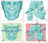
The DICOM files were reconstructed into 3D craniomaxillofacial models by using the Mimics software; thereafter, the three planes that were perpendicular to each other, as the reference planes, were constructed using the 3-matic software. The three planes represented three directions, which are explained in Figure 1 and Table 1. The landmarks were then reoriented by combining the multiplanar views and 3D reconstruction models. In total, 45 anatomic landmarks on the reconstructed structures were selected to construct the measurement and analysis models, and 27 linear and angular measurements were performed (Table 2).
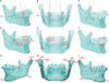
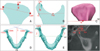
The linear and angular measurements were expressed in millimeters and degrees, respectively, for analyzing the dental parameters, mandibular bone, condyle, and glenoid fossa. Before the main measurement and analysis, the deviation of the maxillary and mandibular midline and facial midline, as well as the side to which the maxillary and mandibular midline had deviated to, were determined. The measurement and analysis was performed in three parts. (1) Tooth measurements (Figure 2 and Table 2), including the mesiodistal and faciolingual crown angulation of the first molar, were performed for assessing the 3D incline of the first molar; the sagittal position of the first molar was measured for identifying the anteroposterior position of the asymmetry of the first molar. (2) The length of the mandibular body, height of the ramus, and length of the entire mandible represented the 3D morphology of the mandibular bone (Figure 2 and Table 2). (3) The measurements of the condyle and glenoid fossa (Figure 3 and Table 2), including the condylar and glenoid fossa morphology, were performed by measuring the height of the condylar head, height of the condylar process, condylar volume and area, width and depth of the glenoid fossa, and angle of the posterior wall of the articular tubercle. The 3D position of the condyle and glenoid fossa was estimated by measuring the angle between the mediolateral plane of the condyle and the sagittal plane, the vertical distance from the geometric center of the condyle to the coronal plane, and the distance from each point (GlA, GlS, and Poi) to the sagittal, coronal, and axial planes.
Statistical analysis
To assess the repeatability of the parameter measurements before the main analysis of data, 16 patients were selected randomly from among the 32 subjects. Anatomic landmarks on the 3D reconstructed models were reoriented by the same researcher fortnightly. The intraclass correlation coefficient (ICC) was used for explaining the intrarater reliability of landmark repositioning; the ICC was obtained by comparing separately the values of each point on the axial, coronal, and sagittal planes.
As for the measurements of dental parameters, mandibular bone, condyle, and glenoid fossa, paired-samples t-tests were used to compare the average differences between the Class I side and Class II side. The Pearson correlation coefficient (r) was calculated separately for each measurement variable that showed significant average differences between the two sides in order to determine whether the variables were linearly associated with each other. All statistical tests were set at 95% confidence level (p < 0.05).
RESULTS
The intrarater reliability ranged between 0.971 and 0.993, indicating a high reliability for landmark identification in this study.
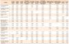
The results of the statistical analysis of the deviation of the maxillary and mandibular midline and facial midline are listed in Table 3. In the study samples, patients with maxillary midline deviation to the Class II side accounted for 75% and those with deviation to the Class I side accounted for 25%. Patients with mandibular midline deviation to the Class II side accounted for 87.5% and those with deviation to the Class I side accounted for 12.5%. The mean distance of mandibular midline deviation to the Class II side (1.73 mm) was greater than the mean distance of maxillary midline deviation to the Class II side (0.18 mm). The mean distance of maxillary midline deviation to the Class I side (0.63 mm) was greater than the mean distance of mandibular midline deviation to the Class I side (0.54 mm).
The means and standard deviations for the differences between the Class I and Class II sides for all variables, as well as the results of the t-tests, are listed in Table 4. A comparison of the dental measurements between the Class I and Class II sides revealed statistically significant differences for the faciolingual crown angulation of the mandibular first molar (p < 0.05) and the sagittal position of the maxillary (p < 0.01) and mandibular (p < 0.01) first molars. When the average values of the two sides were compared, the faciolingual crown angulation of the mandibular first molar on the Class II side was smaller than it was on the Class I side. The distance between Mx6R and the coronal plane on the Class II side was comparatively greater than it was on the Class I side. However, with respect to the mandibular first molar, the distance between Mn6R and the coronal plane on the Class II side was comparatively smaller than it was on the Class I side.
A comparison of the measurements of the condyle and glenoid fossa between the Class I and Class II sides revealed that the height of the condylar head (p < 0.01), height of the condylar process (p < 0.05), angle of the posterior wall of the articular tubercle (p < 0.01), and coronal position of GlA (p < 0.01), GlS (p < 0.01), and Poi (p < 0.05) were significantly different. The mean values of condylar head height and condylar process height on the Class II side were significantly smaller than those on the Class I side. The mean values of the angle of the posterior wall of the articular tubercle and distance between GlS, GlA, and Poi to the sagittal plane on the Class II side were greater than those on the Class I side. However, no significant differences were observed between the Class I and Class II sides when the condylar volume, condylar area, width of the glenoid fossa, depth of the glenoid fossa, sagittal position of the glenoid fossa, axial position of the glenoid fossa, angle between the mediolateral plane of the condyle and the sagittal plane, and vertical distance from the geometric centers of the condyles to the coronal plane were compared. In addition, no statistically significant differences were observed in the comparisons of mandibular body length, ramus height between the two sides, and the full mandibular length.
Pearson correlation coefficients for the variables showing statistically significant differences between the Class I and Class II sides are listed in Table 5. The height of the condylar head presented a significantly positive correlation with the sagittal position of the mandibular first molar (p < 0.05). The condylar volume was positively correlated with the height of the condylar process (p < 0.05). The depth of the glenoid fossa presented a significantly negative correlation with the height of the condylar process (p < 0.01). The sagittal position of the mandibular first molar was positively correlated with the sagittal position of the maxillary first molar (p < 0.01). The condylar area was positively correlated with the condylar volume (p < 0.01) and negatively correlated with the depth of the glenoid fossa (p < 0.05). The angle of the posterior wall of the articular tubercle presented a significantly positive correlation with the depth of the glenoid fossa (p < 0.05).
DISCUSSION
This study used CBCT for measuring and analyzing Class II subdivision malocclusion patients with asymmetry. CBCT is an effective tool for clinical examination. It allows more accurate visualization of complicated anatomic structures with less radiation exposure, shorter scan time, and lower operating cost than does conventional multislice CT,1415 especially for analyzing TMJ morphology, bone defects, and position.16 Compared with current cephalometric and panoramic imaging techniques, CBCT was relatively unaffected by skull location.17 However, Neiva et al.18 have shown that highly reliable values were obtained more often with multiplanar reconstruction models than with 3D reconstruction models. Lower reliability was found for points on the condyle. Depending on the anatomic region, CBCT multiplanar and 3D reconstructions had different reliability values in different anatomic regions. To reduce the errors in positioning, this study used a combination of multiplanar and 3D-reconstructed images for reorienting the landmarks.
Most previous studies using 2D or 3D radiography have shown that an asymmetrical molar position between the sides could contribute to Class II subdivision malocclusion. Sanders et al.5 indicated that the movement of the maxillary first molar to a mesial position and movement of the mandibular first molar to an opposite position contributed to this malocclusion. Janson et al.13 and Azevedo et al.,2 however, described the primary and secondary relationships between maxillary and mandibular first molar positioning on the Class II side and concluded that distal movement of the mandibular first molar was the main factor and mesial movement of the maxillary first molar was a minor factor contributing to malocclusion. These findings were similar to those of the present study, showing that asymmetrical molar position of the maxillary and mandibular first molars existed in Class II subdivision malocclusion. In order to evaluate further the maxillary or mandibular asymmetry, we measured the maxillary and mandibular midline; our findings suggest that mandibular dentoalveolar asymmetry was the primary contributor and maxillary dentoalveolar asymmetry was the secondary contributor to malocclusion. Regarding the 3D changes to the teeth, the mandibular first molar showed significant lingual inclination and a tendency towards distal inclination, whereas the maxillary first molar showed a tendency towards mesial and facial inclination on the Class II side. This indicated that Spee's curve and mediolateral curve of the posterior tooth were deeper on the Class II side than on the Class I side. Pinho had reported the successful treatment of a Class II subdivision malocclusion by controlling the occlusal plane.19 Therefore, when orthodontists treat this type of malocclusion, they should pay more attention to posterior tooth asymmetry and the occlusal plane.
Because different researchers have used different structures and measurements when analyzing the skeletal characteristics of Class II subdivision malocclusion, their results are varied. Sanders et al.5 insisted that the morphology and position of the mandibular bone showed asymmetry between the two sides, which resulted in the primary asymmetry of Class II subdivision malocclusion. They also concluded that sagittal position changes of the maxillary and mandibular first molars on the Class II side played a minor role in this type of asymmetric occlusion.5 However, Minich et al.6 held the opposite view, and some researchers even suggested there was neither a bony deformity nor a mandibular asymmetry between the Class II and Class I sides.20 In this study, the mandibular body height, ramus height, and full mandibular length did not differ significantly between the two sides, but condylar head and condylar process heights on the Class II side were remarkably smaller than those on the Class I side. The most superior and inferior points of the glenoid fossa of the temporal bone and the most inferior point of the external acoustic meatus were significantly laterally positioned. Therefore, it was possible that condylar morphology and glenoid fossa position asymmetry, instead of the mandibular bone, produced the major skeletal asymmetry. Similarly, Li et al.7 concluded that the skeletal asymmetry in Class II subdivision malocclusion appeared more frequently on the glenoid fossa, particularly in the position of the glenoid fossa.
TMDs are common jaw disorders and usually include various signs and symptoms, such as pain in the TMJ or jaw muscles, abnormal joint sounds on mandibular movement, as well as restricted movement of the mandibular bone.2122 TMDs have been associated with condylar position in the glenoid fossa,23 as well as bony and morphological changes of the condyle.24 Slavicek25 indicated that the 3D position of the mandibular bone was affected by the contact relationship of the teeth, and that structural adaptation of the TMJ was related to the eruption and coupling of permanent teeth. Therefore, all patients with Class II subdivision malocclusion included in the current study had to meet one of the following inclusion criteria: over 18 years of age and the eruption of all permanent teeth, excluding the third molars. According to some studies, different types of malocclusion have different condylar morphologies and positions of the condyle in the mandibular fossa. Anterior positioning of the condyle (non-concentric position) in the glenoid fossa has been illustrated in Class II division 1 and Class III malocclusions.910 A smaller condyle and wider spaces between the condyle and glenoid fossa has been reported in Class II malocclusion,12 together with a significantly lower condyle volume as compared to that in Class I and Class III malocclusions.13 In this study too, we observed smaller condyles and wider spaces between the condyle and glenoid fossa on the Class II side than on the Class I side. Larger condyles were considered to have stronger resistance against displacement. If the glenoid fossa and condyle had a good contact, they could effectively support the alteration of the occlusion. Nevertheless, whether the TMJ structures would produce adaptive changes easily on the Class II side and whether these patients with Class II subdivision malocclusion could run a higher risk of developing TMDs should be investigated in large-scale follow-up studies.
Our results regarding the relationship between mandibular first molar position and the condyle-glenoid fossa suggested that the condylar height was smaller when the mandibular first molar showed greater distal movement, and the glenoid fossa simultaneously moved deeper. Tanne et al.26 showed that the great compressive stresses produced in the anterior and lateral regions of the mandibular condyle subsequently increased with the vertical skeletal discrepancy. The decrease in condylar height and increase in glenoid fossa depth might be due to the stresses between the condyle and glenoid fossa exerted during the process of mandibular molar distal movement. Therefore, we concluded from these results that the progression of the morphological and pathological status of the condyle and glenoid fossa was related to the position of the first molar. Accordingly, when orthodontists are treating patients with Class II subdivision malocclusion without any extraction or asymmetric extraction,272829 these potential TMJ problems should be taken into consideration. Mesial movement of the mandibular first molar and uprighting the long axis of the mandibular first molar maybe suitable treatment approaches.
CONCLUSION
Distal positioning as well as significant lingual inclination of the mandibular first molar and mesial positioning of the maxillary first molar on the Class II side were dental characteristics of Class II subdivision malocclusion with asymmetry.
Condylar morphology and glenoid fossa position asymmetries, rather than the mandibular bone, acted as major components of skeletal asymmetry in Class II subdivision malocclusion.
Condylar and glenoid fossa morphology was significantly correlated with the 3D position of the first molar.


 XML Download