

 PDF
PDF ePub
ePub Citation
 Print
Print


INTRODUCTION
Malposition of acetabular and femoral components in total hip arthroplasty (THA) can cause complications, such as containment, impingement, wear, loosening, dislocation, and decreased postoperative range of motion.1234567 To prevent these complications, most orthopedic surgeons use the safe zone, as suggested by Lewinnek, et al.,8 with a cup inclination of 40° (±10°) and cup anteversion of 15° (±10°), as well as the concept of combined anteversion (the sum of cup and stem anteversions).910
Femoral neck anteversion (FNA), the angle between the distal femoral condylar axis and the femoral neck axis, is usually measured in the process of preoperative planning of stem anteversion before THA.11 Intraoperative version of the femoral component is generally determined through a visual appraisal of the stem position relative to the distal femoral condylar axis.1612 However, several studies have shown that even experienced surgeons show a high probability of misinterpreting their visual assessments of stem positions during THA because of the limited availability of bony landmarks in the femoral neck and proximal femur.613141516 Jerosch, et al.17 suggested an 11° mean error between pre- and postoperative anteversion. The midcortical line described by Suh, et al.,18 which connects the anterior and posterior cortical walls of a cutting plane, was also not considered true femoral anteversion.4 Stem anteversion was also found to be particularly difficult to control in cementless THA.121013
FNA can be estimated using various radiographic measurement methods, such as simple radiography, fluoroscopy, magnetic resonance imaging, or computed tomography (CT).1920 Of these techniques, the use of axial planes from CT scans has been widely adopted for measuring FNA. However, measurements taken in two-dimensional (2D) axial planes have proven less consistent.21 On the other hand, measurements taken on three-dimensional (3D) CT images could be a gold standard for obtaining reliable measurements of the femoral component regardless of patient positioning.22
Nevertheless, preoperative planning using 3D images to reconstruct bone models can be limited by the lack of a technique that applies the results of preoperative planning during THA. A CT-based navigation system for THA has recently enabled accurate acetabular and femoral component positioning and improved long-term survival.23 However, surgeons should fix a pelvic tracker on the iliac crest and a femoral tracker on the anterolateral region of the distal femur. As another method to obtain precise stem anteversion, surgeons have used patient-specific instruments (PSIs) produced based on 3D reconstructed images of an individual patient's bone structures. Recent studies have indicated that PSI can be used with high accuracy to avoid femoral component malpositioning.242526 However, when using PSIs alone, obtaining real-time feedback about intraoperative stem positioning during THA can be difficult.
To overcome the drawbacks of the navigation system and PSI, we used both techniques to realize accurate stem anteversion. Although several studies have compared the accuracies of the conventional method and the navigation system or PSI, none has used both techniques together. Therefore, we aimed to investigate the accuracy and consistency of the CT-based navigation system with PSI, compared to those of the conventional technique using visual estimation by the surgeon.
MATERIALS AND METHODS
Study design
This in vitro study used 60 femur sawbones (SKU #1130-100; Sawbones, Vashon Island, WA, USA) to investigate the accuracy and consistency of the proposed technique of a CT-based navigation system with PSI. A GE Lightspeed Ultra 16 CT system (GE Healthcare, Little Chalfont, UK) tuned to 85 kVp was used to obtain a CT scan of a femur sawbone model. Each image was 0.625 mm thick and had a 1024×1024 image matrix. Two orthopedic surgeons (Jun-Young Kim and Shin-Yoon Kim) designed the pre-experimental plan, and two engineers (Seongpung Lee and Jaesung Hong) created the software for the CT-based navigation system. An orthopedic surgeon (Jun-Young Kim) performed 30 femoral neck osteotomies using the conventional technique and another 30 femoral neck osteotomies using the proposed technique. Femoral medullary canals were identified with a box chisel in both groups by the same surgeon. The order of the femoral neck osteotomy and femoral medullary canalizing for the 60 models was decided randomly.
Conventional technique
No pre-experimental preparation was performed for the conventional technique. Each femoral neck osteotomy was conducted using an oscillating saw. After the femoral neck osteotomy, we performed femoral medullary canalizing using the box chisel. Stem anteversion was determined by visual assessment of the stem position relative to the distal femoral condylar axis in all 30 sawbones. No reference tool was used to perform the femoral neck osteotomy or the femoral medullary canalizing procedures.
Proposed technique
Before the in vitro study of 30 sawbones was performed, a preparation process was conducted that included the following six procedures: 1) obtaining a CT scan of a sawbone model; 2) segmentation and reconstruction of a 3D bone model; 3) measurement and set-up of the femoral anteversion of the 3D reconstructed bone model; 4) PSI design and 3D printing; 5) preregistration between the coordinate systems of the 3D reconstructed bone model and optical tracking system (OTS; Polaris Spectra, Northern Digital Inc., Waterloo, Canada) using the landmarks on PSI after attaching a marker (PM); and 6) chisel calibration for tracking the tip of the box chisel after attaching a marker to the box chisel (CM) using a self-developed marker adapter.27
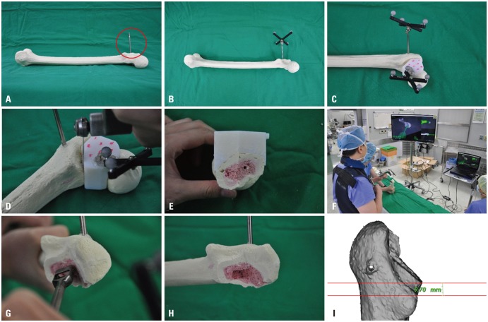
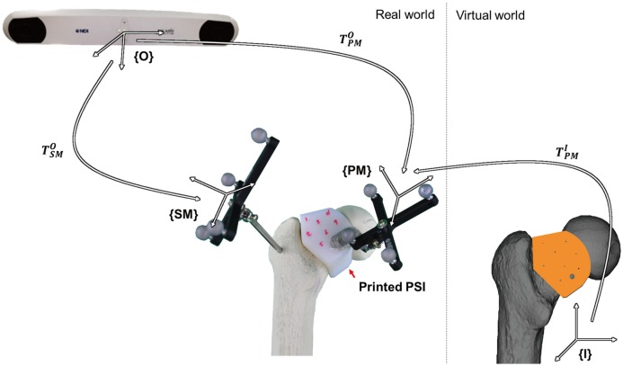
After completing the pre-experimental preparation process, we conducted the in vitro study using the proposed technique as follows (Supplement Video 1, only online). First, a Steinmann pin with a marker (SM) was firmly fixed at the greater trochanter of the sawbones. Second, the PSI was inserted at the planned position. Third, one-click image-to-patient registration using the PSI was performed without additional steps, such as choosing a landmark with a digitizing probe. Fourth, the femoral neck osteotomy was conducted along the margin of the PSI. Finally, femoral medullary canalizing was performed using the box chisel with the navigation system (Fig. 1).
Measuring femoral anteversion
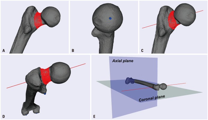
A virtual femur model was reconstructed from CT images of the sawbone model using a 3D slicer (Brigham and Women's Hospital, Boston, MA, USA). On the virtual model, femoral anteversion was measured using the proprietary software (Daegu Gyeongbuk Institute of Science and Technology) (Fig. 2). This anteversion can be also measured using commercially available software, such as the Mimics® software package (Materialise, Leuven, Belgium).
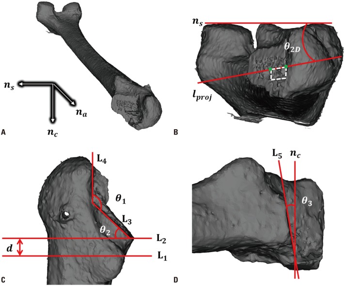
Points around the femoral neck were chosen manually. The center of the chosen points was calculated (Fig. 2A). A different center point on the femoral head in the lateral view was also chosen manually (Fig. 2B), and two center points were used to determine a reference line (lr) (Fig. 2C). Axial, sagittal, and coronal planes were redefined to provide a coherent coordinate system for the femur in every CT scan on the sawbone model (Fig. 2D and E). First, the coronal plane was determined using the medial and lateral condyles and the lesser trochanter. Second, the sagittal plane was determined using an axis that was determined using the two condyles. Finally, the axial plane was determined based on the cross product of two normal vectors of the sagittal and coronal planes.
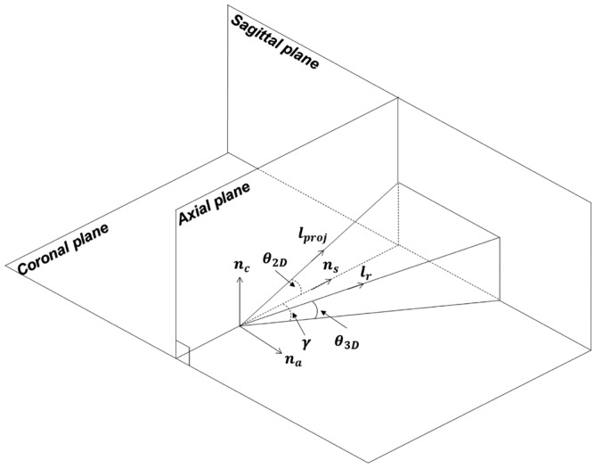
The 2D and 3D anteversions (θ2D and θ3D) are defined as follows (Fig. 3):
where na, ns, and nc are the normal vectors of the axial, sagittal, and coronal planes; lr is the reference line. In this study, the θ2D and θ3D values of the reconstructed sawbone model were 4.5° and 4.1°, respectively.
PSI design
The PSI, which offers guidance during femoral neck osteotomy, as well as fast and accurate image-to-patient registration in the operating room, was designed based on the virtual femur model. The Mimics® software package (Materialise) was used in this study.
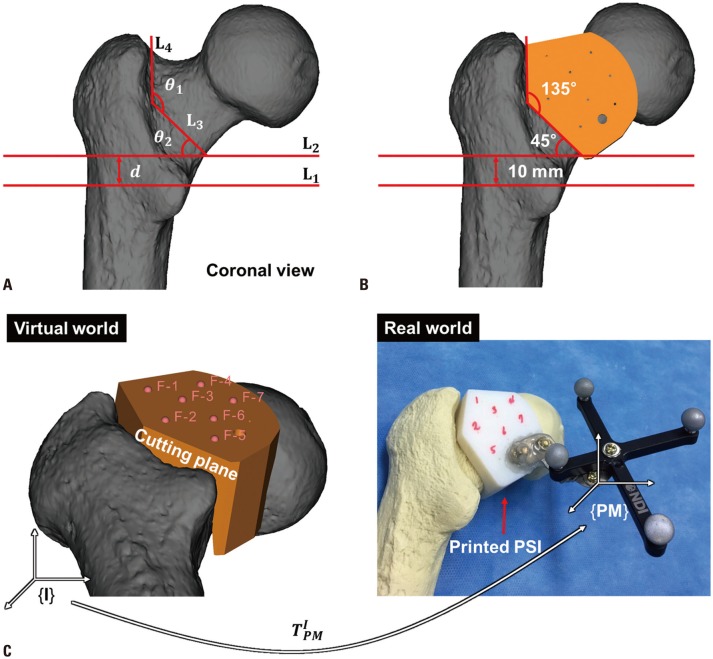
Four cutting lines (L1, L2, L3, and L4) were manually drawn in the coronal view (Fig. 4A). L1 was first drawn parallel to the axial plane, passing through the upper one-third of the lesser trochanter. L2 was drawn parallel to L1 with d. Once L2 was drawn, L3 was drawn at θ2 relative to L2. Finally, L4 was drawn at θ1 relative to L3. In this study, θ1, θ2, and d were set to 135°, 45°, and 10 mm, respectively. The cutting plane was orthogonal to both na and ns and parallel to nc; thus, an angle between the cutting plane and nc (θ3) was set to 0°. In keeping with these rules, the PSI was designed to be precisely positioned on the femoral neck (Fig. 4B and C).
Preregistration using PSI
Image-to-PM registration was preoperatively performed using a PSI.2829 For image-to-PM registration, seven virtual landmarks were made on the PSI with a hole (Fig. 4B) and their coordinates were saved. The printing was performed with the PSI using a 3D printing machine with a 16-micron-layer accuracy (Objet Eden 250, Stratasys, Eden Paririe, MN, USA) (Fig. 4C). A PM was attached to the PSI, and seven points with respect to the PM were chosen using a digitizing probe. Using these seven paired points, TIPM was calculated with the pairedpoint registration (PPR) technique.30
One-click image-to-patient registration
In the operating room, the PSI was placed on the planned surface after SM fixation (Fig. 5). While the SM and PM were simultaneously tracked by the OTS, image-to-patient registration was simply performed by clicking a button on the user interface of the navigation system, because the transformation from image to SM (TIPM) was given by the following equation: where TOPM and TOSM represent transformations from the OTS to the PM and from the OTS to the SM, respectively, which were directly acquired from the OTS; TIPM is already obtained before.
Navigation system for femoral component insertion
The main functions of the self-developed navigation system are to measure the orientation of the calibrated box chisel and to provide visual feedback in real time. One-click image-to-patient registration is also available.
The orientation of the box chisel with respect to the SM is measured using Eqs. (1) and (2). The planned femoral anteversion and the box chisel orientation are simultaneously displayed on the navigation system. When the orientation of the box chisel is measured within the planned femoral anteversion±safe margin, the color of the virtual model of the box chisel is changed from the color the user set initially to green. The safe margin for visual feedback was set to 2°.
Evaluation of the proposed technique
After finishing the surgical procedures using both techniques on the 60 sawbones, postoperative CT images of the 60 sawbones were taken and reconstructed into virtual femur models using a 3D slicer. For comparison with the planned information, the registration step was performed between the 60 virtual femur models and the virtual femur model used in the planning step. The common coordinate system on the 60 virtual femur models is drawn in Fig. 6A.
The repeatability of femoral neck osteotomy and femoral medullary canalizing on both techniques was evaluated using the registered virtual femur models. For every registered virtual model, a manually drawn line passing through two edge points of a rectangular hole made from femoral medullary canalizing was defined as lproj (Fig. 6B). Using Eqs. (1) and (2), 2D and 3D anteversions were calculated. θ1, θ2, θ3, and d were also defined in each model. To define all except θ3, L3 and L4 were first drawn along the cut line in the coronal view (Fig. 6C). Second, L1 was drawn in the same manner as the planned one. Finally, L2 was drawn parallel to the axial plane and passed through the intersection point between L3 and the contour of the model. L5 was drawn to define θ3 in the sagittal view (Fig. 6D). Errors in all factors (2D and 3D anteversions, θ1, θ2, θ3, and d) were calculated using the corresponding planned information.
Statistical analysis
The study included 60 femur sawbones subjected to CT. We analyzed the mean and standard deviation (SD) of 2D anteversion, 3D anteversion, θ1, θ2, θ3, and d. To obtain the optimal sample size, we used the G-Power program (a free statistical program available at http://www.gpower.hhu.de/). The significance level (α), statistical power (1-β), and effect size (f) were set at 0.05, 0.8, and 0.3, respectively. We used Bland-Altman diagrams to analyze the agreement between the conventional and proposed techniques.31 All statistical analyses were performed using IBM Statistics 22.0 (IBM Corp., Armonk, NY, USA).
RESULTS
Measurement of 2D and 3D anteversion
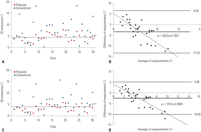
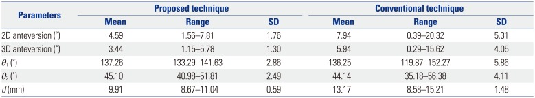
The means of the proposed and conventional techniques were 4.59° (SD, 1.76°; range, 1.56–7.81°) and 7.94° (SD, 5.31°; range, 0.39–20.32°) for 2D anteversion (Table 1, Fig. 7A) and 3.44° (SD, 1.30°; range, 1.15–5.78°) and 5.94° (SD, 4.05°; range, 0.29–15.62°) for 3D anteversion (Table 1, Fig. 7C).
In determination of the absolute deviation between the measured and reference values, the mean 2D anteversions of the proposed and conventional techniques were 1.41° (SD, 1.03°; range, 0.02–3.32°) and 4.78° (SD, 4.12°; range, 0.38–15.83°) (Table 2, Fig. 7B), respectively, while the 3D anteversions were 1.15° (SD, 0.85°; range, 0.02–2.91°) and 3.31° (SD, 2.96°; range, 0.02–11.55°) (Table 2, Fig. 7D).
Measurements of θ1, θ2, θ3, and d
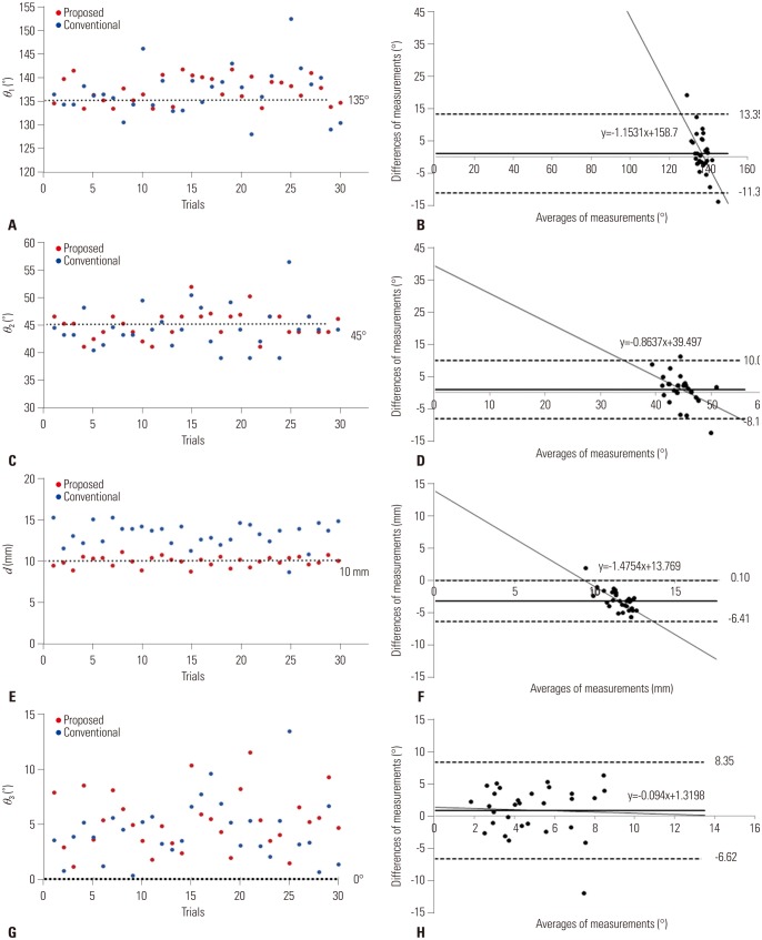
Mean θ1, θ2, and d were 137.26° (SD, 2.86°; range, 133.29–141.63°), 45.10° (SD, 2.49°; range, 40.98–51.81°), and 9.91 mm (SD, 0.59 mm; range, 8.67–11.04 mm) with the proposed technique and 136.25° (SD, 5.86°; range, 119.87–152.27°), 44.14° (SD, 4.11°; range, 35.18–56.38°), and 13.17 mm (SD, 1.48 mm; range, 8.58–15.21 mm) (Table 1, Fig. 8A, C, and E) with the conventional technique.
In the determination of the absolute deviation between the measured and reference value, the mean θ1, θ2, θ3, and d were 2.93° (SD, 2.14°; range, 0.07–6.63°), 1.96° (SD, 1.48°; range, 0.18–6.81°), 5.29° (SD, 2.66°; range, 1.15–11.59°), and 0.48 mm (SD, 0.40 mm; range, 0.01–1.45 mm) with the proposed technique and 4.26° (SD, 4.14°; range, 0.25–17.27°), 3.17° (SD, 2.69°; range, 0.48–11.38°), 4.43° (SD, 2.79°; range, 0.35–13.52°), and 3.15 mm (SD, 1.24 mm; range, 0.62–5.08 mm) with the conventional technique (Table 2, Fig. 8B, D, F, G, and H).
DISCUSSION
Precise alignment of the femoral component during THA is important, because excessive anteversion or retroversion can cause posterior impingement and anterior instability or anterior impingement and posterior instability.311 Increased anteversion of the femoral component can also increase bending moments, hip contact forces, and torsional moments; as a result of the change, the rates of femoral component loosening can increase.3233 Although many orthopedic surgeons have determined intraoperative stem anteversion by visual evaluation of the stem position, there is a high probability that visual estimation is unreliable. Wines, et al.14 reported that the differences between intraoperative visual evaluation and CT measurement were up to 30° for stem anteversion, while Hirata, et al.5 showed that the differences were >5° in 60% of cases. Dorr, et al.13 described that visual evaluations differed by ±10° compared to CT measurement.
For that reason, several studies have examined femoral component positioning using a navigation system. Dorr, et al.15 demonstrated that mean femoral component anteversion and postoperative CT measurements were 10.9°±9.0° and 10.6°±8.0° using a CT-free navigation system, respectively; while Kitada, et al.34 reported values of 31.1°±11.7° and 31.7°±11.7° using a CT-based navigation system. However, surgeons should affix a pelvic tracker to the iliac crest and a femoral tracker to the anterolateral region of the distal femur for registration of the navigation system. Although no study has reported intra- and postoperative complications, such as infection and fracture around the tracker sites, we believe that femoral component positioning using a CT-based navigation system without the need for additional incisions and tracker fixation could be a better method.
The use of PSI is another method to ascertain exact positioning of the femoral component. PSIs were introduced as a substitute for high-cost and time-intensive navigation systems. Ito, et al.26 demonstrated that precise stem anteversion within 5° was achieved in seven of 10 cases. However, PSI use has a few shortcomings. First, it requires solid fixation with the femur at the planned position. If the position is inaccurate due to soft-tissue impingement or unstable fixation, the probability of measurement errors will increase. Second, it cannot provide surgeons with real-time feedback about intraoperative stem position during THA. Since postoperative stem position, especially in cementless THA, can be influenced by stem designs and anatomical shapes, such as the bow and twist of the proximal femur, real-time information regarding femoral component positioning is essential.113 Therefore, to resolve each drawback of the navigation system and PSI, we developed a CT-based navigation system with PSI to provide accurate femoral component positioning. No study has directly compared the conventional technique to the CT-based navigation system with PSI. To our knowledge, our study is the first to compare the accuracy and consistency of the two techniques.
The accuracy and consistency of the femoral neck osteotomy and femoral medullary canalizing were compared between the proposed and conventional technique. Our results revealed no significant difference in θ3, a vertical error in the coronal plane. One of the reasons of this phenomenon is probably the existence of an SM. As shown in Fig. 1, the SM may disturb the sawing direction because of its size and position. θ1, θ2, θ3, and d can be influenced by the SM. Compared to the proposed technique, no disturbance from the SM was observed in the conventional technique. Therefore, surgeons could more conveniently perform the femoral neck osteotomy. In the experiments, the femoral neck osteotomy was performed while the sawbones were laid straight on the operating table. These factors may yield a positive result for θ3 in the conventional technique.
Although the proposed technique showed significant improvements in performance, except for θ3, our study had several limitations. First, during femoral medullary canalizing, the position of CM could be changed from the initial position due to repetitive hammering. This change could invalidate the chisel calibration results. Although we firmly fixed CM to the adapter, its strength was insufficient. Therefore, a box chisel with CM in a single structure is required to reduce the effect caused by the hammering. Second, we prepared the proximal medullary canal using only a box chisel. Various authors have pointed out that, especially in cementless THA, the stem virtually finds its way to an anteversion position, where it fits best to the rigid canal of the femur.121013 Therefore, our study results could be misled by the assumption that the preparation of the proximal femoral canal with a box chisel is correlated to the final stem position. However, because of that point, intraoperative measurements of the stem position are more important for optimized stem anteversion. Imai, et al.35 reported that shorter tapered wedge stems were more flexible than metaphyseal fit stems in rotation according to the anatomical configuration of the proximal femur. Although we did not research the final stem position using the proposed technique in this study, we will continue examining THA stems using the proposed technique in the future. Third, we observed slight differences in shape among the sawbones. The outcome was obviously affected by these differences because the PSI based on a sawbone model was not perfectly fitted to the sawbones. This problem, however, would not occur in clinical application because a PSI is designed according to each patient's individual anatomy. Although we validated the 60 femur sawbones using a single femur geometry and repeated the same experiment 60 times, the rationale for navigation and PSI is to measure/control component position according to the patient's individual situation. Fourth, the one-click registration took only a few seconds if OTS positioning was well done. However, the proximity of SM and PM caused interference between each other, which resulted in a lot of time-taken for OTS positioning. Use of multi-faced markers might help with reducing time. Fifth, assigning the coronal plane can be difficult. The coronal plane includes the most prominent posterior points of both femoral condyles and the greater trochanter. Because the coronal plane can change according to the coordinate value of the point, marking this point is important. In this study, we selected the lesser trochanter as the most posterior point of the greater trochanter; the authors of another study have chosen a different point on the greater trochanter.23 Therefore, the point should be marked according to each patient's anatomy. Finally, when inserted into the greater trochanter, a Steinmann pin would bear a risk of soft-tissue morbidity and fracture in an operative setting. However, transosseous repair of the posterior capsulotendinous structures has been widely used to overcome this shortcoming of a higher dislocation rate of the posterior approach to the hip joint.36 In transosseous repair, the gluteus medius can be partly damaged by proximal drill holes at the tip of the greater trochanter; however, this shortcoming can be overcome if drill holes are moved to a more distal portion. We also believe that the risk of fracture can be decreased by the use of a smaller drill bit and a single drill hole.
In conclusion, we have proposed a technique using a CT-based navigation system with PSI for femoral component positioning. The proposed technique was more accurate and consistent than the conventional technique, except for a vertical error in the coronal plane, in our experimental in vitro sawbone model. Therefore, we propose that our CT-based navigation system with PSI can be a good option for decreasing the rate of incorrect stem position assessments and enabling accurate stem anteversion determination. A study of the effects of different femur geometries and THA stems under the influence of the soft tissues will be needed in the future.


 XML Download