

 PDF
PDF ePub
ePub Citation
 Print
Print


INTRODUCTION
Close to 80% of the Western population will experience low back pain at some point during their lifetime2). Although most treatment options start with conservative treatments (e.g., steroid injections, physical therapy, chiropractic adjustment), the number of surgical cases performed every year for severe and chronic low back pain is constantly increasing2). Of the different surgical options, spinal fusion has been established as one of the most successful surgical treatments and is considered the clinical standard of care for low back pain surgery9). However, this procedure is not without controversy. Spinal fusion has been reported as a risk factor for accelerated intervertebral disc degeneration at adjacent levels 6141628). Posterior dynamic stabilization is designed to partially preserve the intersegmental kinematics and reduce the adverse changes of loading patterns at the adjacent levels, often seen after fusion surgery. Recently, several in-vitro studies have been published to investigate the biomechanical behavior of the human spine after dynamic stabilization818192034). However, these studies were focused on a comparison between the biomechanics of existing dynamic stabilization devices and fusion. Also, some of these cadaveric studies concluded that dynamic stabilization resulted in similar biomechanical behavior which is achieved with rigid instrumentation 52930). These findings are in direct contrast to the numerical simulations, which indicate a reduced risk of transition syndrome with dynamic stabilization315). A reason for this discrepancy is most likely due to the major limitation associated with applying experimental boundary conditions during biomechanical testing. More specifically, a force control mode was applied, resulting in a constant pure bending moment. No matter what procedure is performed at the treatment level, the pure bending moment along the spinal column results in the same spinal kinematics at the adjacent levels, which can be explained purely by definition. Nevertheless, if a patient performs the same activity of daily living (ADL) before and after surgery, the overall spine kinematics will not change, although segmental changes do occur. Furthermore, the rigidity of the dynamic stabilization device is considered the primary variable affecting intersegmental spinal kinematics. However, to our knowledge, no previous in-vitro studies have investigated the effect of the dynamic stabilization device rigidity on biomechanical behaviors of the spine. The objective of this current study is to evaluate the effect of dynamic stabilization with varying rigidity on human spinal kinematics and to determine the relationship between implant rigidity and transition syndrome.
MATERIALS AND METHODS
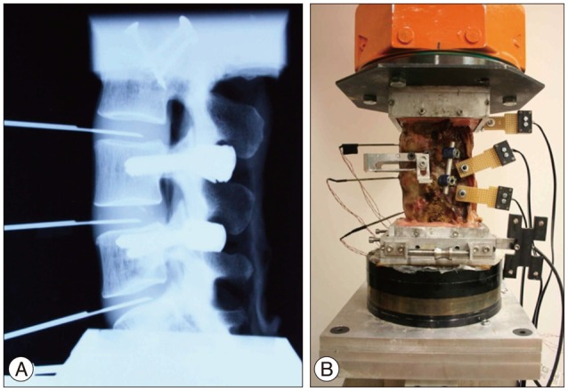
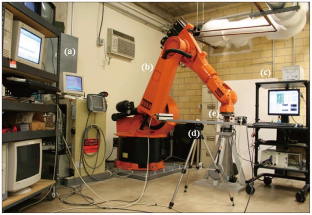
Five human cadaveric spines (58.2±2.31 years) from L3 to sacrum were harvested from three female and two male donors. Muscular and fatty tissues were removed from the vertebrae, leaving the transverse processes, facet joints, posterior elements, and ligaments intact. Casting cement (PMMA) was used to mount the specimens cranially and caudally with L4 aligned horizontally. Titanium polyaxial pedicle screws (6.5 mm in diameter, 45 mm long, Pangea screw system, Synthes Inc., West Chester, PA, USA) were inserted bipedicularly in the L4 and L5 vertebrae. X-ray images were taken of each specimen at the sagittal plane using a portable X-ray unit (Bowie MFG. Inc., Lake City, IA, USA). This was done to identify any bone fractures that might be present and to verify the pedicle screw locations. Needle pressure transducers (Denton ATD Inc., Rochester Hills, MI, USA) were placed anteriorly at all three levels and it was confirmed by radiographic images that the pressure transducer was placed in the middle of the intervertebral disc (Fig. 1A). The pressure transducers had a sensing area with 0.06 inches (1.5 mm) in diameter which was located at 0.16 inches (4.1 mm) proximal to the distal end of the needle (13 gauge). As each specimen was tested, intervertebral disc pressure at each level was collected by a data acquisition system (PXI 1010, National Instruments Corporation, Austin, TX, USA). The custom bio-robotic testing system was comprised of a 6 degree of freedom (DOF) robotic arm (KR150, KUKA Robotics Corporation, Clinton Township, MI, USA) and a 6 DOF force/torque transducer (Omega160, ATI Industrial Automation, Apex, NC, USA). In an effort to closely simulate natural flexion and extension motions, the robotic system followed a circular arc motion pathway. Relative motion of the vertebrae was studied using an optical tracking system (PcReflex, Qualisys Inc., East Winsor, CT, USA) which recorded data when the specimens were flexed, neutral, and extended. Marker arrays with four active infrared light emitting diodes were attached to the spinous process of the L4 and L5, the articulating arm of the robot, and the reference base (Fig. 1B). The integrated testing system is illustrated (Fig. 2).
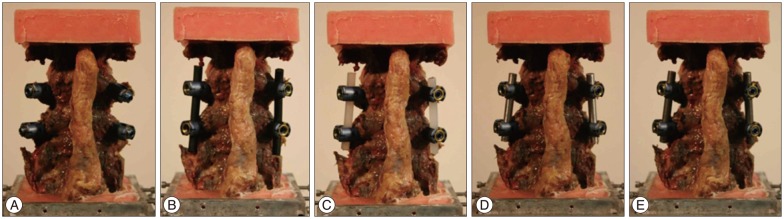
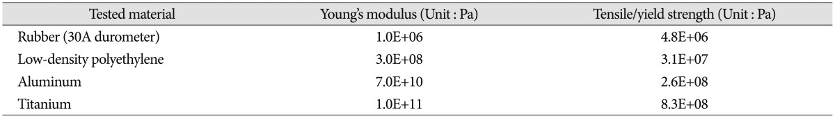
The range of motion (ROM), center of rotation (COR), and intervertebral disc pressure were measured for each vertebral functional unit (L3-4, L4-5, L5-S1) during flexion/extension testing. Specimens were tested under two axial loading conditions : 0 N and 400 N. The axial load was then transferred to the cable system, positioned bilaterally along the specimen through U-shaped brackets. This was done to prevent buckling of the specimens during high axial force testing and is based on the follower load concept1223). To evaluate different elastic moduli of the implant system, five different materials were tested : intact (without rod), rubber (RU), low-density polyethylene (LDPE), aluminum (Al), and titanium (Ti) with each measuring at 6.25 mm in diameter (Fig. 3). Mechanical properties of the tested materials are described in Table 110). The independent input parameters, including overall ROM and COR, were investigated using pre-surgical radiographic image sets of 33 patients (15 male and 18 female) who underwent surgical treatments due to L4-5 disc degeneration, stenosis, and/or spondylolisthesis. These patients also had higher ROM at L4-5 than 1/3 (33%) of the overall ROM from L3 to S1. The pre-operational images were taken, on average, 0.62 months before the surgery. The patient analysis showed that an overall ROM for L3-S1 of 19.70° for flexion and 7.70° for extension is optimal. Overall CORs for L3-S1 for the patients were at the center, just below the L4-5 intervertebral disc. In order to mimic similar overall motion and behavior, the total ROM (19.70° and 7.70° for flexion and extension, respectively) was forced to remain constant. Even though each specimen had a different morphogenic structure, constant overall COR was applied through geometric measurements from radiographic images. This process allowed direct comparison between samples that would not have been possible otherwise. Furthermore, this process also increased the statistical power for subsequent analyses. Before biomechanical testing began, each specimen received sufficient pre-conditioning to reduce viscoelastic effects21). Each specimen completed 5 cycles of flexion and extension motions. Each testing material and each experiment started with the intact specimen and continued with the 4 different materials tested in randomized order.
The parameter calculation followed a statistical evaluation. The initial statistical test determined if there was a significant difference in mean ROM and pressure between all intact cadaveric specimens in flexion and extension in order to allow the data to be pooled. A paired t-test with equal sample size and a two-tailed distribution was utilized. In the second stage, one-factor and two-factor ANOVA studies with repeated measures were implemented to account for differences in treatment group (intact and 4 implants) and boundary conditions (flexion/extension and 0 N or 400 N axial preload). In case a statistically significant difference was found, further paired t-test analyses to determine in depth relative changes in ROM and disc pressure relative to specific implant types were applied.
RESULTS
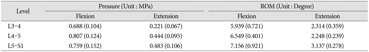
The measured intervertebral disc pressure and ROM of the intact spine with pre-load are shown (Table 2). No statistical significant difference was observed (p>0.05) between samples. Since the applied overall spinal ROM was kept constant to allow comparison with the analyzed patients' characteristics, the measured disc pressure and ROM at each level tended to be less than those for full motions. However, the disc pressures were within the same order of magnitude as those found in the published articles2732), and the ROMs showed the same proportional tendency with full motion studies2433). These disc pressure and ROM datasets of the intact cases at each level were used to normalize the experimental results to a common reference point.
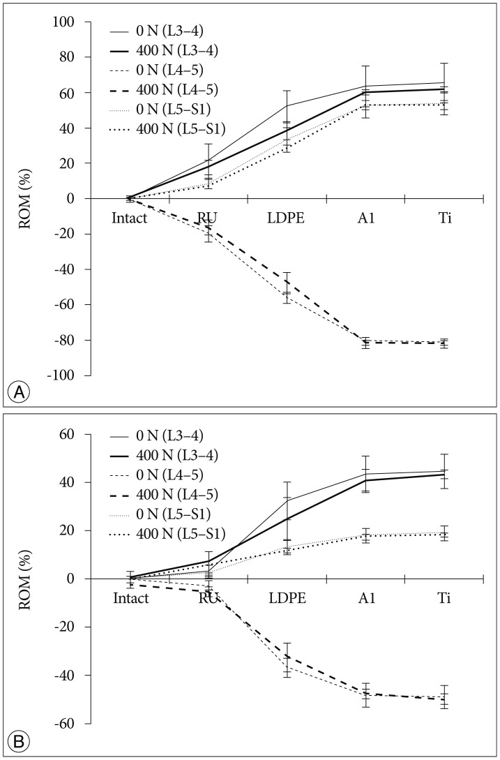
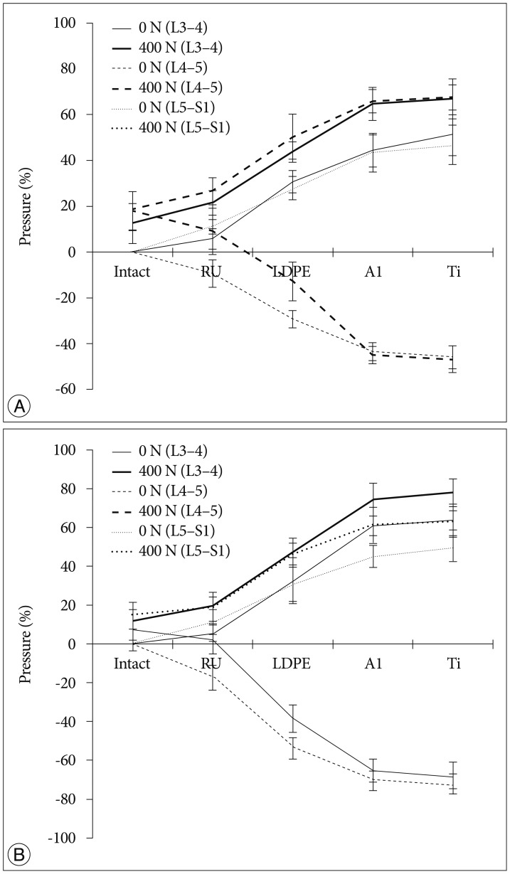
The tendency that both the ROM and disc pressure at the treated levels decreased is illustrated below. Those values increased at the adjacent levels as the rigidity of the interconnecting rod material increased (Fig. 4, 5). The five materials, which represented different degrees of elasticity, are shown in increasing rigidity from left to right. Comparing PE, Al, and Ti with the intact test showed significant difference on both the ROM and disc pressure at all levels. Flexion and extension data showed similar tendencies and patterns in the tests of ROM and disc pressure. Implant stiffness saturation was evident as the ROM and disc pressure were only marginally increased beyond the implant stiffness of aluminum. Even though the stiffness of the implant increased, ROM and pressure were not significantly increased for the Al and Ti cases. The magnitude of ROM of the untreated spinal segments was not significantly different at 0 N and 400 N axial loads for the Al and Ti treated level.
The two-factor ANOVA with repeated measures indicated significant differences in ROM (p<0.001) when all loading conditions and implant types were compared. Interestingly enough, the interaction term was not significantly different (p=0.545) for the measured disc pressure but was significantly different for the ROM. The reduced two-factor ANOVA test indicated a statistical significant dependence on implant type but not to the applied axial preload in extension. In flexion, the boundary conditions influenced the statistical model (p=0.008). However, in both cases, the interaction term was not statistically significant (p=0.994 and p=0.232, respectively). In further, limiting the statistical analysis to just the two axial preload cases, all independent parameters (motion type and implant type) were significantly related to ROM. The interaction terms for both analyses (0 N and 400 N axial preload) were significant (p<0.001). The single factor ANOVA test for all four cases (combination of 0 N or 400 N axial preload and flexion or extension movement) was statistically significant (p<0.001).
An additional detailed paired analysis of individual groups revealed that the soft rubber implant did not reduce the ROM of the treated spinal segment significantly in extension (0 N and 400 N) and flexion (0 N). Rather, reduction of the ROM occurred in the 400 N axial compression and flexion cases. All other implant configurations reduced the ROM significantly differently for all loading cases and all motion patterns (p<0.001). The probability values for the two-factor ANOVA test with repeated measures related to the dependence of disc pressure on implant type, motion patterns, and axial compression were almost identical, except for the interaction terms, which were never significantly different for the pressure analysis. For the detailed analysis, a two-tailed paired analysis was chosen for the disc pressure within the treated segment, compared to the one-tailed analysis related to the ROM tests. In general, the stiffer implants stress shielded the intervertebral disc more than the softer implants. The rubber implant did not cause a significant reduction in disc pressure (p>0.05). However, all the other implants showed a statistical significant decrease in disc pressure at the treated level (p<0.05).
As expected, we observed a tendency that the disc pressure measured for low implant rigidity at 400 N axial load was higher than that without axial load, as the preload increased the base load of the pressure sensor (Fig. 3). However, at high implant rigidity, such as aluminum and titanium, the difference in disc pressures between the 0 N and 400 N axial loading cases at L4-5 was minimal. At the adjacent levels, the disc pressure difference between the 0 N and 400 N axial loading cases seems to be insensitive to variations in dynamic stabilization implant rigidity, with the shape of the curve dominated by the effect of implant rigidity variation.
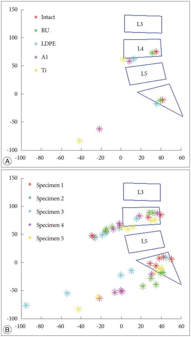
Intersegmental CORs at the adjacent levels such as L3-4 and L5-S1 were depicted (Fig. 6). The dataset of one specimen was represented (Fig. 6A), and it describes the segmental COR to move anteriorly and inferiorly at the adjacent disc levels as rigidity of the device increased. It was clearly shown that the same tendency was observed within the data of all specimens (Fig. 6B).
DISCUSSION
We experimentally tested four different implant materials and a control case without implants with the goal of characterizing spinal kinematics after dynamic stabilization by varying the implant rigidity and physiological loading condition. For ease of comparison, the overall ROM was kept constant for all analyses. In general, in-vitro study utilizes load control (i.e., pure moments of 12.5 Nm or 10 Nm)582029). Load control may not reflect a patient's desire to move their spine with the same repeated pattern before and after treatment. In contrast, displacement control, meaning the same deflection endpoint for different cases, is commonly simulated in finite element (FE) analyses31). To achieve the same level of position control within an experimental setup, we utilized a 6 DOF robotic arm in displacement control. This allowed us to verify the generated results with theoretical data obtained from FE analysis.
The results of this in-vitro experimental study validated the numerical findings and provided excellent agreement with respect to the transition syndrome413). The ROM and disc pressures of the adjacent levels became higher with increasing stiffness of the dynamic stabilization implant. In order to compensate for the loss of motion in L4-5 due to the rigidity of the implant rods, the segments above and below needed to overcorrect as the overall ROM was kept the same throughout the experiment. Since rubber had a low stiffness, it tended to show a similar biomechanical behavior as the experimental case without rods. In addition, the spinal kinematics after dynamic stabilization with the aluminum rod was only marginally different from the cases where the titanium rods were used. Both cases had a segmental rigidity that was much higher than the intact segmental stiffness of the spine.
The more rigid implants supported more of the applied compressive loading compared to the softer implants. It was shown that when a compressive load was applied, disc pressures in the aluminum and titanium cases at the L4-5 spinal level tended to be closed to those of 0 N axial loading (Fig. 5). This finding was corroborated by the numerical studies published by Ahn et al.1). The authors were also in favor of reducing load sharing of the implant when using dynamic stabilization. Additionally, there was a tendency that disc pressures of the adjacent levels at 400 N axial loading were higher than those without pre-load. We believe that this was because the axial load was transferred along the specimen by the bilateral cable system. Since the same total ROM was applied and uniform loading was applied at all segments, ROM in different loading conditions observed a similar performance (Fig. 4).
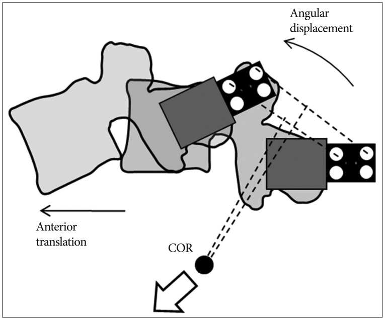
Furthermore, this study indicated that segmental COR tended to move anteriorly and inferiorly at L3-4 and L5-S1 as rigidity of the device increased. Since the overall ROM and COR were kept constant during the experiments, angular displacement and anterior translation increased at the adjacent levels in order to compensate the loss of L4-5 movement when the device was stiffer. The compensatory effect of increased angular displacement and anterior translation made the COR move anteriorly and inferiorly in the adjacent levels (Fig. 7). It is known that segmental COR is normally located in the posterior half of the intervertebral disc or the inferior vertebra112226). Comparing this with the normal behavior, the displacement of COR due to rigid implant might be able to indicate significant secondary injury risks such as facet joint overloading and accelerated intervertebral disc degeneration717).
There were several limitations associated with this study. Pearcy et al.25) reported that large errors occurred in calculation of COR when the segmental movement was less than 5 degrees. Because of these expected limitations, we did not analyze the CORs for extension motion and the treatment level (L4-5). Since the overall ROM of the specimen was known, the L4-5 segmental COR could be approximated. Nevertheless, this would just propagate the error from the COR calculations of the other two segments to the treatment level.
Another limitation of this study was the reduced ROM analysis just within the sagittal plane. Although the robotic system could determine ROM along the 360 degree circumference, such analysis has not been done before, and a normal circumferential ROM standard would need to be established. Future studies will need to ascertain the 3D ROM of the human spine, which will ultimately advance our understanding how the human spine functions and how medical devices impede spinal kinematics.
Despite the above listed limitations, we believe that this study provides a significant step forward in delineating the relationship between implant rigidity and changes in ROM and COR at adjacent levels. What's remarkable is that even relatively soft implants (polyethylene) caused a significant shift in COR away from the physiological range. This result questions the concept of replacing a titanium connecting rod of a fusion system with a softer material in order to achieve dynamic stabilization.
CONCLUSION
Depending on physiological loading, implants will provide different biomechanical functionality in recovering or preserving motion after treatment. A major contributing factor on spinal kinematics can be the stiffness or rigidity of an implant. We described that increasing implant rigidity resulted in reduced segmental mobility at the treatment level, while at the same time increasing the compensation mechanism at the adjacent levels. With the aid of the pressure sensors, we verified that the rigidity of the posterior dynamic stabilization implants influenced the load sharing between the implant and the spinal column. The results indicated that the COR transitioned outside the physiological limit when very rigid implants were used, and this transition was more pronounced in the inferior adjacent level than in the superior adjacent level. The changes in COR may put the patient at an increased risk to secondary injury or disc degeneration at adjacent levels. These findings will be able to aid in further device development for dynamic stabilization and help to interpret long-term clinical outcomes of dynamic stabilization.
 XML Download